4 unipolar/bipolar -21, 4 unipolar/bipolar – Maxim Integrated MAXQ7666 User Manual
Page 111
MAXQ7665/MAXQ7666 User’s Guide
3-21
3.3.4 Unipolar/Bipolar
The MAXQ7665/MAXQ7666 ADC produces a digital output that corresponds to the differential analog input voltage as long as the dif-
ferential analog inputs are within the specified range. The analog inputs are configured for differential conversion when the ADCDIF
control bit is set. When performing differential conversions, the control bit ADCBIP in analog control register selects between unipolar
and bipolar operation modes. Unipolar mode sets the differential input range from 0 to REFADC (for PGA gain of 1, it is less if the gain
is > 1). A negative differential analog input in unipolar mode causes the digital output code to be 0. Selecting bipolar mode sets the
differential input range to -REFADC/2 to +REFADC/2 (for PGA gain of 1, it is less if the gain is > 1). The digital output code is straight
binary in unipolar mode and two’s complement in bipolar mode (see
Section 3.3.5: Transfer Function).
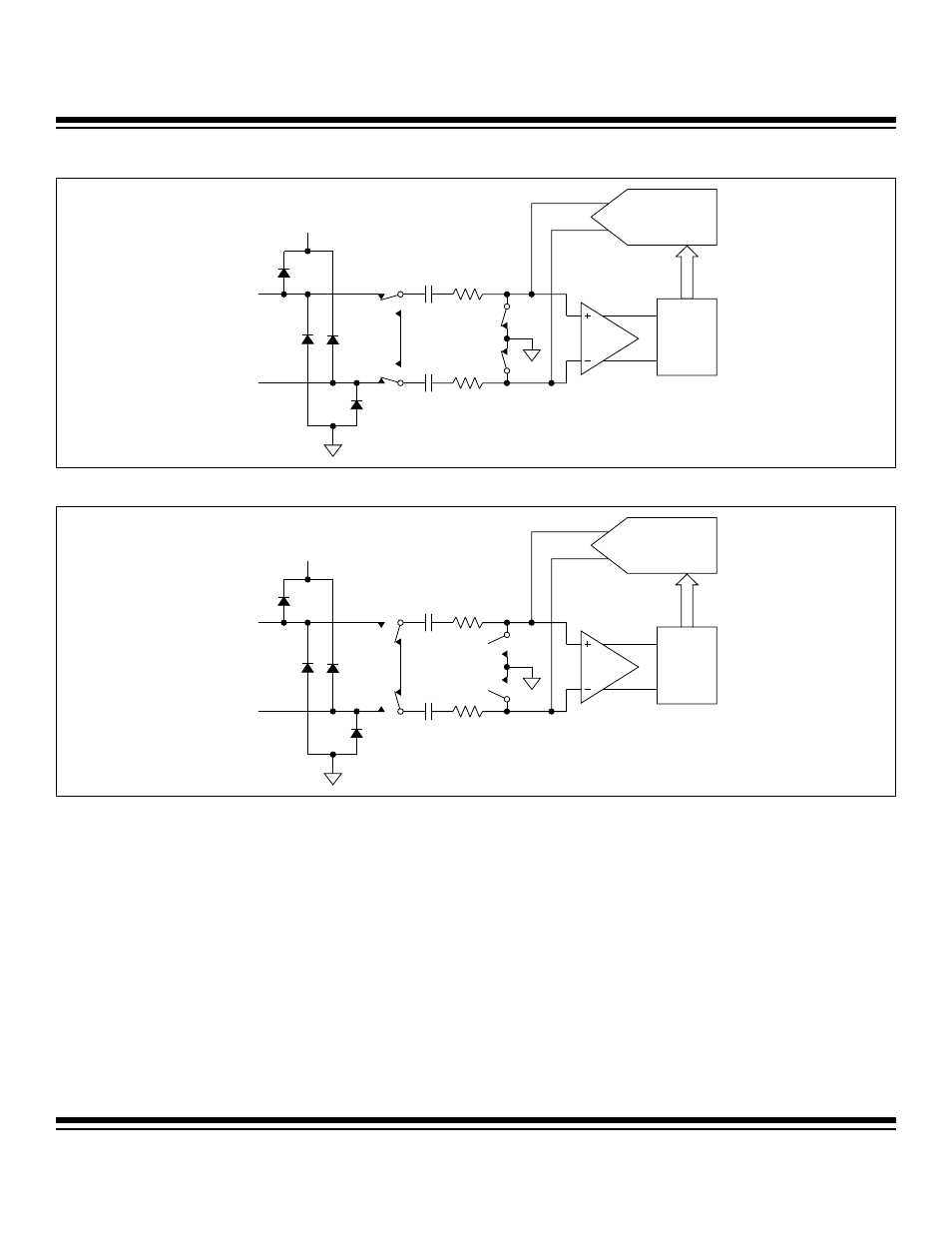
Figure 3-4A. Equivalent Input Circuit (Acquisition Mode with PGA Bypassed)
CONTROL
LOGIC
CAPACITIVE
DAC
AGND
AIN+
AIN-
CIN+
CIN-
RIN+
RIN-
COMP
AVDD
CONTROL
LOGIC
CAPACITIVE
DAC
AGND
AIN+
AIN-
CIN+
AVDD
CIN-
RIN+
RIN-
COMP
Figure 3-4B. Equivalent Input Circuit (Hold/Conversion Mode with PGA Bypassed)
Maxim Integrated