1 hardware multiplier organization -2, 1 hardware multiplier organization – Maxim Integrated MAXQ7666 User Manual
Page 329
MAXQ7665/MAXQ7666 User’s Guide
13-2
SECTION 13: HARDWARE MULTIPLIER MODULE
The MAXQ7665/MAXQ7666 microcontrollers include a hardware multiplier module to support high-speed multiplications. The hardware
multiplier module is equipped with two 16-bit operand registers, a 32-bit read-only result register, and an accumulator of 48-bit width.
The multiplier can complete a 16-bit x 16-bit multiply-and-accumulate/subtract operation in a single cycle. The hardware multiplier
module supports the following operations without interfering with the normal core functions:
• Signed or Unsigned Multiply (16 bit x 16 bit)
• Signed or Unsigned Multiply-Accumulate (16 bit x 16 bit)
• Signed or Unsigned Multiply-Subtract (16 bit x 16 bit)
• Signed Multiply and Negate (16 bit x 16 bit)
13.1 Hardware Multiplier Organization
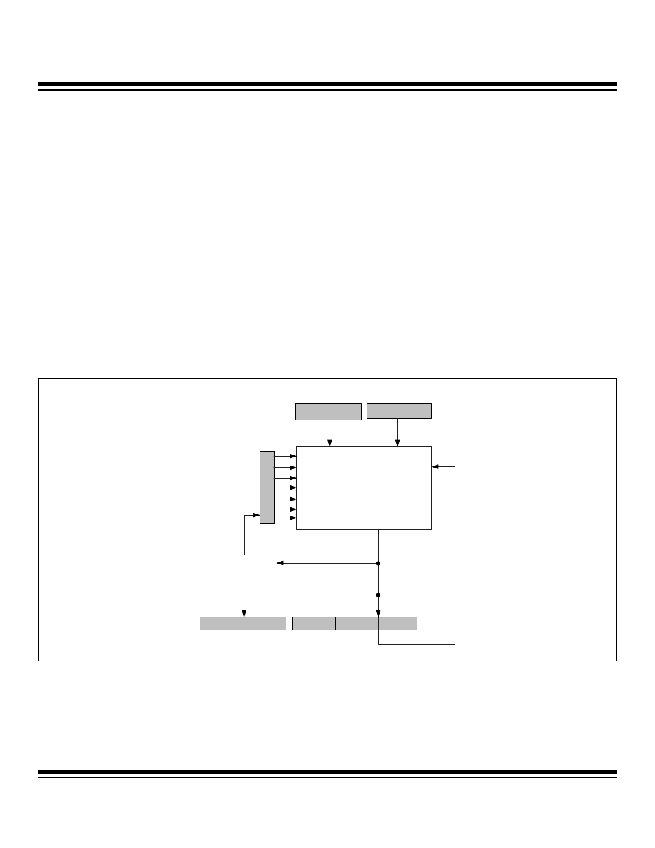
The hardware multiplier consists of two 16-bit, parallel-load operand registers (MA, MB); a read-only result register formed by two par-
allel 16-bit registers (MC1R and MC0R); an accumulator, which is formed by three 16-bit parallel registers (MC2, MC1, and MC0); and
a status/control register (MCNT). Figure 13-1 shows a block diagram of the hardware multiplier.
The main arithmetic unit is the 16-bit x 16-bit multiplier that processes operands feeding from the MA and MB registers and generates
a 32-bit final product. The multiplier unit includes an adder that can be used to perform a final accumulate/subtract operation of the
multiplier output with the MC2:MC0 registers. The MCNT register must be configured to select the desired operation and operand count
prior to loading the operand(s) to trigger the multiplier operation.
MB
MA
MC0
MC1
MC2
MULTIPLIER
0
0
15
15
0
15
0
15
OVERFLOW
SUS
MMAC
MSUB
OPCS
SQU
CLD
MCW
15
0
15
15
0
0
MC1R
MC0R
MCNT
Figure 13-1. MAXQ7665/MAXQ7666 Multiplier Organization
Maxim Integrated