4 interrupts -23, 4 interrupts, 1 servicing interrupts – Maxim Integrated MAXQ7666 User Manual
Page 25
MAXQ7665/MAXQ7666 User’s Guide
1-23
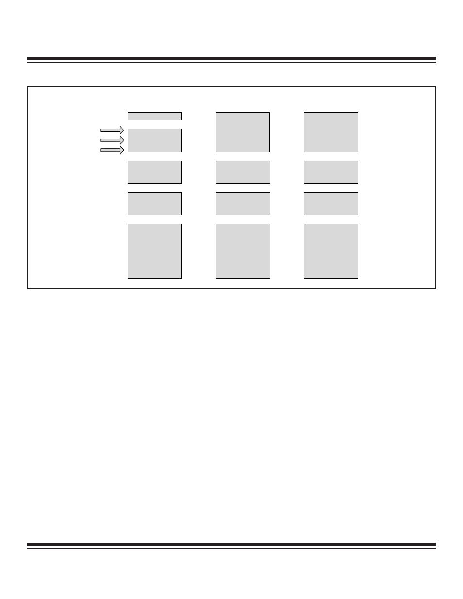
PROGRAM
SPACE
DATA SPACE
(BYTE MODE)
DATA SPACE
(WORD MODE)
8k x 16
PROGRAM FLASH
0000h
1FFFh
16k x 8
PROGRAM FLASH
(CDA0 = 0)
0000h
3FFFh
8k x 16
PROGRAM FLASH
0000h
1FFFh
4k x 16
UTILITY ROM
8FFFh
4k x 16
UTILITY ROM
8000h
407Fh
128 x 16
DATA FLASH
4000h
4k x 16
UTILITY ROM
9FFFh
8k x 8
UTILITY ROM
8000h
00FFh
256 x 8
DATA FLASH
(CDA0 = 1)
0000h
4k x 16
UTILITY ROM
8FFFh
4k x 16
UTILITY ROM
8000h
407Fh
128 x 16
DATA FLASH
4000h
256 x 16
DATA RAM
A000h
A0FFh
EXECUTING FROM
Figure 1-12. MAXQ7666 Memory Map When Executing from Data RAM
1.2.4 Interrupts
The MAXQ7665/MAXQ7666 provide a single, programmable interrupt vector (IV) that can be used to handle internal and external inter-
rupts. Interrupts can be generated from system level sources (e.g., watchdog timer) or by sources associated with the peripheral mod-
ules included in the specific MAXQ7665/MAXQ7666 microcontrollers. Only one interrupt can be handled at a time, and all interrupts
naturally have the same priority. A programmable interrupt mask register allows software-controlled prioritization and nesting of high-
priority interrupts.
1.2.4.1 Servicing Interrupts
For the MAXQ7665/MAXQ7666 to service an interrupt, interrupts must be enabled globally, modularly, and locally. The Interrupt Global
Enable (IGE) bit located in the Interrupt Control (IC) register acts as a global interrupt mask. This bit defaults to 0, and it must be set
to 1 before any interrupt takes place.
The local interrupt-enable bit for a particular source is in one of the peripheral registers associated with that peripheral module, or in a
system register for any system interrupt source. Between the global and local enables are intermediate per-module and system interrupt
mask bits. These mask bits reside in the Interrupt Mask system register. By implementing intermediate per-module masking capability in
a single register, interrupt sources spanning multiple modules can be selectively enabled/disabled in a single instruction. This promotes
a simple, fast, and user-definable interrupt prioritization scheme. The interrupt source-enable hierarchy is illustrated in Figure 1-13.
When an interrupt condition occurs, its individual flag is set, even if the interrupt source is disabled at the local, module, or global level.
Interrupt flags must be cleared within the user interrupt routine to avoid repeated interrupts from the same source.
Since all interrupts vector to the address contained in the Interrupt Vector (IV) register, the Interrupt Identification Register (IIR) may be
used by the interrupt service routine to determine the module source of an interrupt. The IIR contains a bit flag for each peripheral mod-
ule and one flag associated with all system interrupts; if the bit for a module is set, then an interrupt is pending that was initiated by
that module. If a module is capable of generating interrupts for different reasons, then peripheral register bits inside the module pro-
vide a means to differentiate among interrupt sources.
The Interrupt Vector (IV) register provides the location of the interrupt service routine. It may be set to any location within program mem-
ory. The IV register defaults to 0000h on reset or power-up, so if it is not changed to a different address, the user program must deter-
mine whether a jump to 0000h came from a reset or interrupt source.
Maxim Integrated