14 interrupt vector register (iv) -54, 15 loop counter 0 register (lc[0]) -54, 14 interrupt vector register (iv) – Maxim Integrated MAXQ7666 User Manual
Page 56: 15 loop counter 0 register (lc[0])
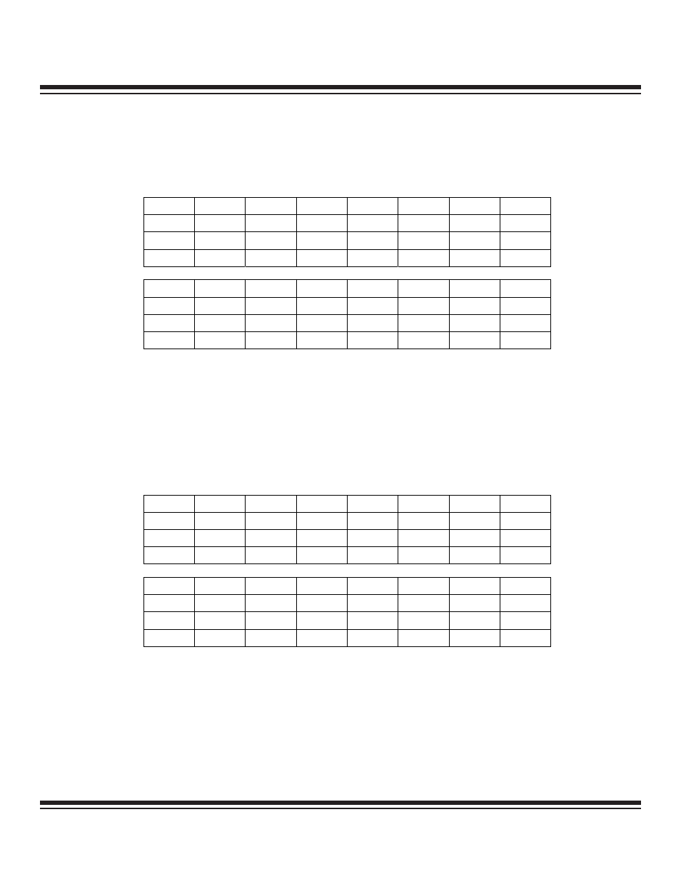
1.4.14 Interrupt Vector Register (IV)
Register Description:
Interrupt Vector Register
Register Name:
IV
Register Address:
Module 0Dh, Index 02h
Bits 15 to 0: Interrupt Vector Register Bits 15 to 0 (IV.15 to IV.0). This register contains the address of the interrupt service routine.
The interrupt handler will generate a CALL to this address whenever an interrupt is acknowledged.
1.4.15 Loop Counter 0 Register (LC[0])
Register Description:
Loop Counter 0 Register
Register Name:
LC[0]
Register Address:
Module 0Dh, Index 06h
Bits 15 to 0: Loop Counter 0 Register Bits 15 to 0 (LC[0].15 to LC[0].0). This register is used as the loop counter for the DJNZ LC[0],
src operation. This operation decrements LC[0] by one and then jumps to the address specified in the instruction by src.
MAXQ7665/MAXQ7666 User’s Guide
1-54
Bit #
15 14 13 12 11 10 9 8
Name
IV.15 IV.14 IV.13 IV.12 IV.11 IV.10 IV.9 IV.8
Reset
0 0 0 0 0 0 0 0
Access rw
rw
rw
rw
rw
rw
rw
rw
Bit #
7
6
5
4
3
2
1
0
Name
IV.7 IV.6 IV.5 IV.4 IV.3 IV.2 IV.1 IV.0
Reset
0 0 0 0 0 0 0 0
Access rw
rw
rw
rw
rw
rw
rw
rw
r = read, w = write
Note: This register is cleared to 0000h on all forms of reset.
Bit #
15 14 13 12 11 10 9 8
Name
LC[0].15 LC[0].14 LC[0].13 LC[0].12 LC[0].11 LC[0].10 LC[0].9 LC[0].8
Reset
0 0 0 0 0 0 0 0
Access rw
rw
rw
rw
rw
rw
rw
rw
Bit #
7
6
5
4
3
2
1
0
Name
LC[0].7 LC[0].6 LC[0].5 LC[0].4 LC[0].3 LC[0].2 LC[0].1 LC[0].0
Reset
0 0 0 0 0 0 0 0
Access rw
rw
rw
rw
rw
rw
rw
rw
r = read, w = write
Note: This register is cleared to 0000h on all forms of reset.
Maxim Integrated