15 bit timing -64, Figure 4-14. bit timing -64, 15 bit timing – Maxim Integrated MAXQ7666 User Manual
Page 194
MAXQ7665/MAXQ7666 User’s Guide
4-64
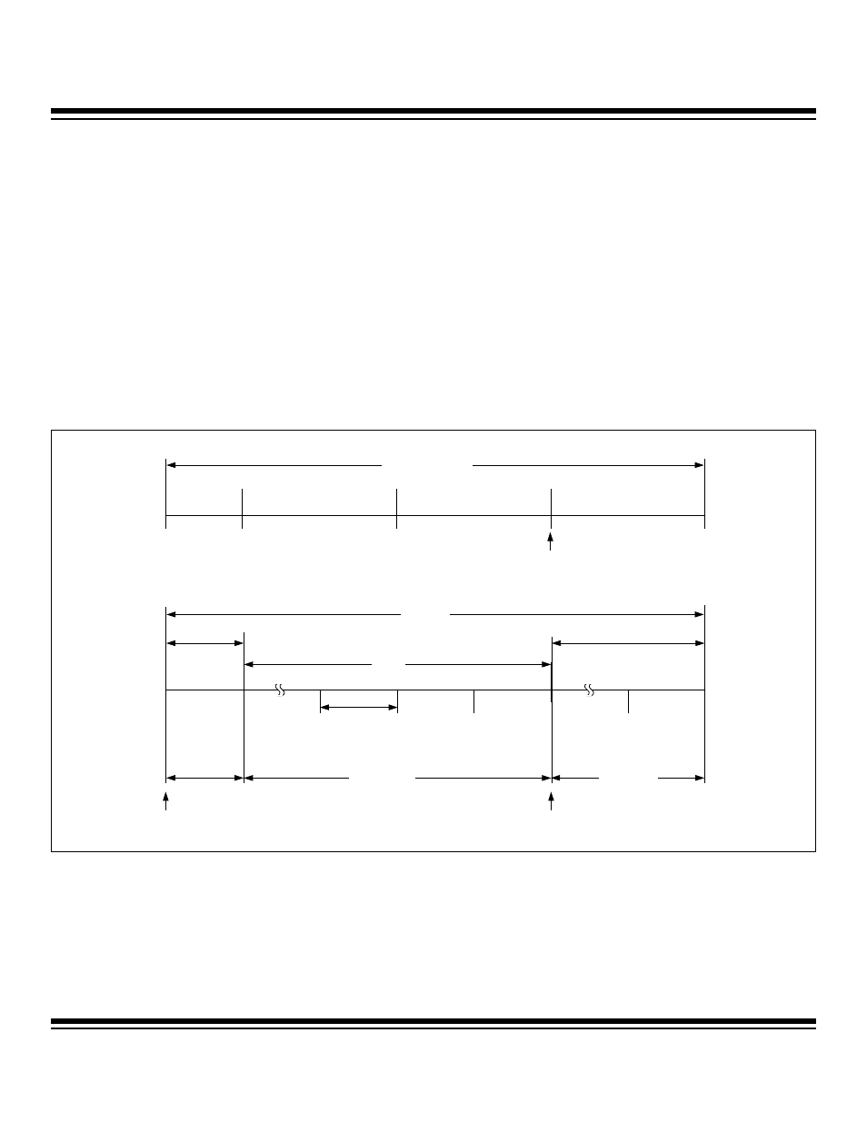
4.15 Bit Timing
Bit timing in the CAN2.0B specification is based on a unit called the nominal bit time. The nominal bit time is further subdivided into
four specific time periods.
1) The SYNC_SEG time segment is where an edge is expected when synchronizing to the CAN bus.
2) The PROP_SEG time segment is provided to compensate for the physical times associated with the CAN bus network.
3) The PHASE_SEG1 and PHASE_SEG2 time segments compensate for edge phase errors.
4) The PHASE_SEG1 and PHASE_SEG2 time segments can be lengthened or shorted through the use of the SJW1 and SJW0 bits
in the CAN 0 bus timing register zero.
The CAN bus bit data is evaluated at a specific sample point. A time quantum (t
QU
) is a unit of time derived from the division of the
microcontroller system clock by both the baud-rate prescaler (programmed by the BPR7:BPR0 bits of the CAN 0 operation control reg-
ister and CAN 0 bus timing register) and the system clock divider (programmed by the CD1:CD0 and PMME bits of the CKCN regis-
ter). Combining the PROP_SEG and PHASE_SEG1 time segments into one time period termed t
TSEG1
, and equating the SYNC_SEG
time segment to t
SYNC_SEG
and PHASE_SEG2 to t
TSEG2
, provides the basis for the time segments outlined in Figure 4-14 and in the
CAN bus timing peripheral register descriptions.
Figure 4-14. Bit Timing
1 BIT TIME
1 t
QU
TIME QUANTA
1 t
QU
TIME QUANTA
TRANSMIT
SYNC_SEG
PROP_SEG
PHASE_SEG1
PHASE_SEG2
NOMINAL BIT TIME
t
SYNC-SEG
t
TSEG1
t
TSEG2
SAMPLE
POINT
SAMPLE
POINT
2 t
QU
- 16 t
QU
2 t
QU
- 8 t
QU
Maxim Integrated