1 data frame -47, 1 start of frame (sof) -47, 2 arbitration field -47 – Maxim Integrated MAXQ7666 User Manual
Page 178: 3 control field -48, 4 data field -48, 5 crc field -48, 6 acknowledge (ack) field -48, 7 end of frame -48, 8 interframe spacing (intermission) -48, Figure 4-5. control field -48
MAXQ7665/MAXQ7666 User’s Guide
4-48
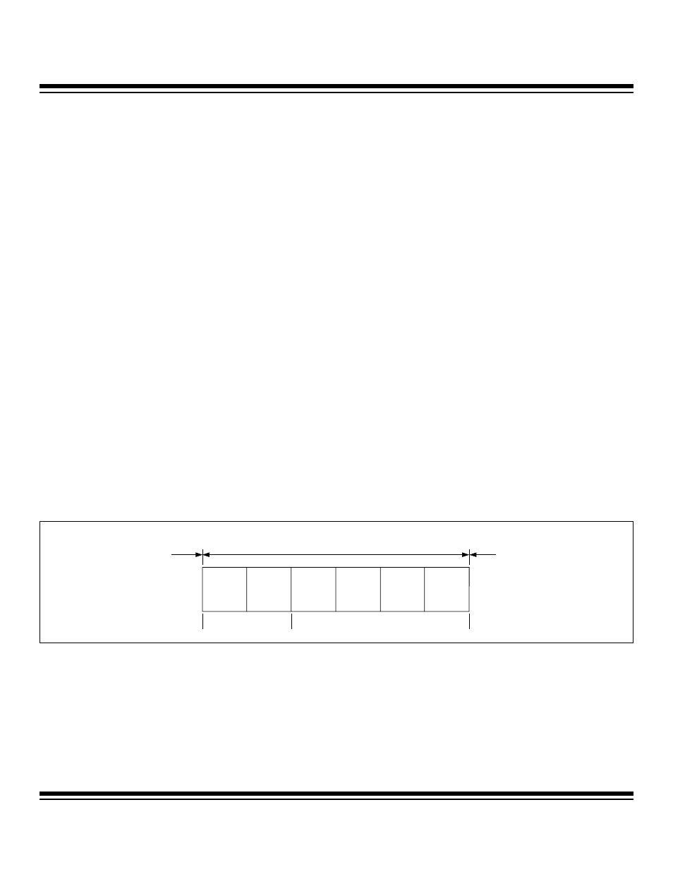
4.3.1.1.3 Control Field
(Standard and extended format.) The control field is composed of six bits in two fields. The first field is made up of two reserved bits
that are transmitted as dominant bits (Figure 4-5). The second field contains four bits that comprise the data length code (DLC). The
DLC determines the number of data bytes in the data field of the data frame, and is programmed through the use of the CAN message
format registers, located in each of the 15 message centers.
4.3.1.1.4 Data Field
(Standard and extended format.) The data field is composed of 0 to 8 bytes in a data frame and 0 bytes in a remote frame. The num-
ber of data bytes associated with a message center is programmed through the use of the CAN message format registers, located in
each of the 15 message centers. The data field contents are saved to the respective message center if the identifier test is success-
ful, no errors are detected through the last bit of the end of frame, and an error frame does not immediately follow the data or remote
frame. The data field is transmitted least significant byte first, with the most significant bit of each byte transmitted first.
4.3.1.1.5 CRC Field
(Standard and extended format.) The CRC field is composed of a 15-bit code that is the computed cyclic redundancy check (after
destuffing bits) from the start of frame, through the arbitration, control, and data fields (when present), and a CRC delimiter (Figure 4-6).
The CRC calculation is limited to a 127-bit maximum code word (a shortened BCH code) with a CRC sequence length of 15 bits.
4.3.1.1.6 Acknowledge (ACK) Field
(Standard and extended format). The ACK field is composed of two bits (Figure 4-7). The transmitting node sends two recessive bits
in the ACK field. The receiving nodes that have received the message and found the CRC sequence to be correct reply by driving the
ACK slot with a dominant bit. The ACK delimiter is always a recessive bit.
4.3.1.1.7 End of Frame
(Standard and extended format). The end of frame for both the data and remote frame is established by the transmitter sending seven
recessive bits.
4.3.1.1.8 Interframe Spacing (Intermission)
(Standard and extended format). Data frames and remote frames are separated from preceding frames by three recessive bits termed
the intermission (Figure 4-8). During the intermission, the only allowed signaling to the bus is by an overload condition. No node is
allowed to start a message transmission of a data or remote frame during this period. If no node becomes active following the inter-
frame space, an indeterminate number of recessive bit times transpires in the bus-idle condition until the next transmission of a new
data or remote frame by a node.
Figure 4-5. Control Field
IDE/r1
r0
DLC3
DLC2
DLC1
DLC0
RESERVED BITS
DATA LENGTH CODE
ARBITRATION
FIELD
CONTROL FIELD
DATA FIELD OR
CONTROL FIELD
Maxim Integrated