4 dual 8-bit timers -21, 5 8-bit timer/8-bit capture mode -21, Figure 7-5. type 2 timer clock -21 – Maxim Integrated MAXQ7666 User Manual
Page 256
MAXQ7665/MAXQ7666 User’s Guide
7-21
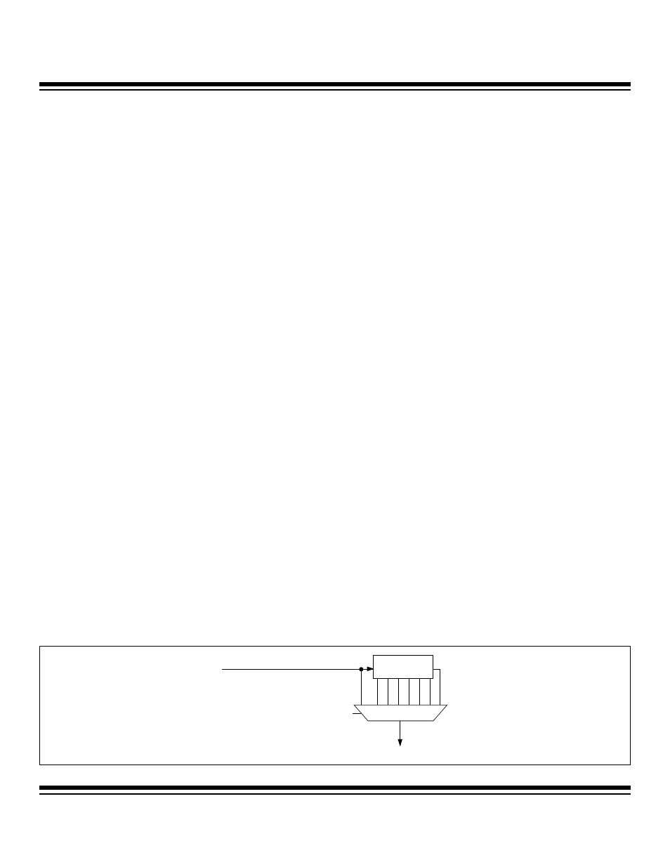
T2DIV[2:0]
SYSTEM CLOCK
T2CLK
DIVIDE-BY-N
PRESCALE
Figure 7-5. Type 2 Timer Clock
7.3.4 Dual 8-Bit Timers
The dual 8-bit timer mode of operation is initiated by setting the T2MD bit to logic 1. When T2MD = 1, each 16-bit register associated
with the Type 2 timer is split into separate upper and lower 8-bit registers to support dual 8-bit timers. Thus, the primary 8-bit timer is
composed of T2Hx (value), T2RHx (reload), T2CHx (capture/compare), and the secondary 8-bit timer is composed of T2Lx (value),
T2RLx (reload), and T2CLx (capture/compare). There is but a single internal Type 2 timer input clock that can be sourced by either of
these two 8-bit timers. The secondary 8-bit timer/counter has its own run control bit (TR2L) and interrupt flags (TF2L, TC2L).
• Output Enable (PWM out). The output enable bit (T2OE0) enables the primary T2Hx 8-bit timer output to be presented on the
Tx pin. T2Lx can only serve as an internal timer.
• Polarity Control. The polarity control bit (T2POL0) can be used to modify (invert) the enabled clock output to the pin. The start-
ing state of the enabled clock output is the logic state of T2POL0 and toggles on each compare match or overflow. The T2POL0
bit is logically XORed with the timer output signal, therefore setting the T2POL0 bit results in a high starting state. The T2POL0
bit can be changed any time, however the assigned T2POL0 state will take effect on the external pin only when the corre-
sponding T2OE0 bit is changed from 0 to 1. When generating PWM output, note that changing the compare match register can
result in a perceived duty cycle inversion if a compare match is missed or multiple compare matches occur during the reload
to overflow counting.
• Gated. To use the Tx pin as a timer input clock gate, the T2OE0 bit must be cleared to 0 and the G2EN bit must be set to 1.
When T2OE0 = 1, the G2EN bit setting has no effect. When T2OE0 is cleared to 0, the respective polarity control bit is used to
modify the polarity of the input signal to the timer. In the gated mode, the input clock to T2Hx is gated anytime that the exter-
nal signal matches the state of the T2POL0 bit. This means that the default clock gating condition is associated with the Tx pin
being low (T2POL0 = 0). Note that the secondary 8-bit timer, T2Lx, cannot be gated.
• Single-Shot. The single-shot bit and mode apply only to the primary 8-bit timer (T2Hx). The single-shot mode is used to auto-
mate the generation of single pulses under software control. To generate single-shot output pulses under software control, the
G2EN bit should be cleared to 0, the output enables and polarity controls should be configured as desired, and the single-shot
bit should be set to 1. Writing the single-shot bit effectively overrides the TR2 = 0 condition until the timer overflow/reload occurs.
Writing SS2 and TR2 = 1 at the same time still causes the SS2 bit to stay in effect until an overflow/reload occurs, however, the
specified PWM output continues since TR2 was also written to 1.
7.3.5 8-Bit Timer/8-Bit Capture Mode
When the CCF1:CCF0 bits are configured to a state other than 00b, the edge capture mode is enabled for the primary timer (T2Hx).
The secondary timer (T2Lx) always remains in the timer/compare mode and does not support any capture functionality. The capture
controls for the 8-bit mode are identical to those specified for the 16-bit mode, however, they apply only to the upper timer, T2Hx.
7.3.6 8-Bit Timer/8-Bit Counter
Just as in the 16-bit mode, setting the C/T2 bit to logic 1 enables the external Tx pin to function as a counter input. The edges that are
counted are determined by the CCF1:CCF0 bits. The counter mode of operation applies only to the primary timer/counter (T2Hx). In a
similar fashion to the 16-bit counter mode, when an overflow occurs, an auto-reload of T2RHx occurs and the TF2 flag is set. The TCC2
flag is also set on a compare match between the T2Hx counter and the T2CHx compare register (except for the case where T2CHx is
outside of the T2RHx to 0xFFh counting range). The secondary timer (T2Lx) always continues to operate in 8-bit compare mode.
7.3.7 Type 2 Timer Input Clock Selection
The Type 2 timer clock source is illustrated in Figure 7-5. System clock is used as the Type 2 timer clock source and is optionally divid-
ed down as defined by the T2DIV2:T2DIV0 bits.
Maxim Integrated