9 analog status register (asr) -15, 9 analog status register (asr) – Maxim Integrated MAXQ7666 User Manual
Page 105
3.2.9 Analog Status Register (ASR)
Register Description:
Analog Status Register
Register Name:
ASR
Register Address:
Module 05h, Index 0Bh
Bit 15: I/O Voltage Brownout Comparator Level (VIOLVL). See
Section 2 for details on this bit.
Bit 14: Digital Voltage Brownout Comparator Level (DVLVL). See
Section 2 for details on this bit.
Bits 13, 12, 10 to 7, 3, and 0: Reserved. Read returns 0, write ignored.
Bit 11: High-Frequency Oscillator Ready (XHFRY). See
Section 5 for details on this bit.
Bit 6: External High-Frequency Oscillator Failure Flag (HFFINT). See
Section 5 for details on this bit.
Bit 5: I/O Voltage Brownout Flag (VIOBI). See
Section 2 for details on this bit.
Bit 4: Digital Voltage Brownout Flag (DVBI). See
Section 2 for details on this bit.
Bit 2: ADC Overrun Flag (ADCOV). This flag signifies that an ADC result overrun has occurred when it is set to logic 1. This bit is
cleared after reading from the ASR register. ADC overrun occurs if prior ADC data gets overwritten before it is read (i.e., ADCRY = 1
at falling edge of ADCBY). If enabled, the ADC overrun interrupt is generated by this register bit.
Bit 1: ADC Data Ready Flag (ADCRY). This flag is set to logic 1 when the ADC completes its conversion and data is ready for access.
This bit is cleared after reading data from the ADCD register. If enabled, the ADC data ready interrupt is generated by this register bit.
MAXQ7665/MAXQ7666 User’s Guide
3-15
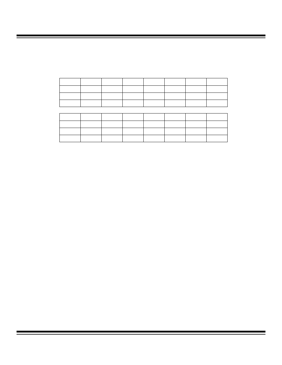
Bit #
15
14
13
12
11
10
9
8
Name
VIOLVL
DVLVL
— —
XHFRY
— — —
Reset
0 0 0 0 0 0 0 0
Access r
r
r
r
r
r
r
r
Bit #
7
6
5
4
3
2
1
0
Name —
HFFINT
VIOBI
DVBI
—
ADCOV
ADCRY
—
Reset
0 0 0 0 0 0 0 0
Access r
r
r
r
r
r
r
r
r = read
Note: The ADCOV bit is cleared by all forms of reset. All other bits are only reset by POR. Reading the ASR register resets to 0 all the status flag bits
except VIOLVL and DVLVL.
Maxim Integrated