Maxim Integrated MAXQ7666 User Manual
Page 243
MAXQ7665/MAXQ7666 User’s Guide
7-8
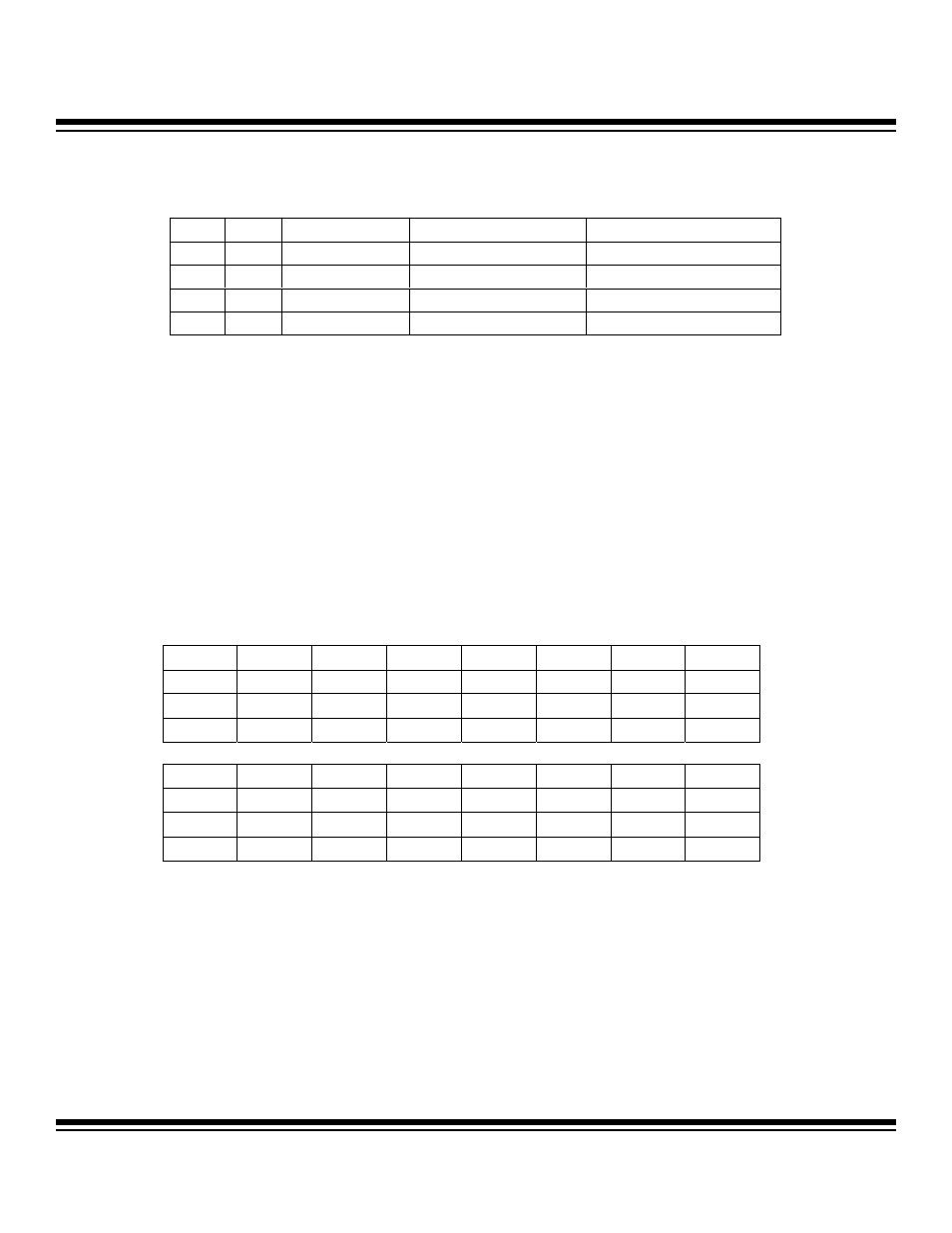
Bits 2 and 1: Capture/Compare Function Select Bits (CCF1 and CCF0). These bits, in conjunction with the C/T2 bit, select the basic
operating mode of the Type 2 timer. In the dual 8-bit mode of operation (T2MD = 1), the T2Lx timer only operates in compare mode.
Bit 0: Counter/Timer Select (C/T2). This bit enables/disables the edge counter mode of operation for the 16-bit counter (T2Vx) or the
8-bit counter (T2Hx) when the dual 8-bit mode of operation is enabled (T2MD = 1). The edge for counting (rising/falling/both) is defined
by the CCF1:CCF0 bits.
0 = timer mode
1 = counter mode
Note: Timer 2 in the MAXQ7665/MAXQ7666 does not support an input/output pin and serves only as an internal timer. Thus, counter
mode (C/T2 = 1) functionality does not apply for timer 2.
7.2.1.2 Type 2 Timer/Counter 2 Control Register A (T2CNAx)
Register Description:
Type 2 Timer/Counter 2 Control Register A
Register Name
T2CNAx (x = 0, 1, 2)
Register Address:
T2CNA0: Module 02h, Index 00h
T2CNA1: Module 02h, Index 04h
T2CNA2: Module 03h, Index 00h
Bits 15 to 8: Reserved. Read 0, write ignored.
Bit 7: Enable Type 2 Timer Interrupts (ET2). This bit serves as the local enable for the Type 2 timer interrupt sources that fall under
the TF2 and TCC2 interrupt flags.
CCF1
CCF0
EDGE(s)
C/T2 = 0 (TIMER MODE)
C/T2 = 1 (COUNTER MODE)
0
0
None
Compare Mode
Disabled
0
1
Rising
Capture/Reload
Counter
1
0
Falling
Capture/Reload
Counter
1
1
Rising and Falling
Capture/Reload
Counter
Bit #
15
14
13
12
11
10
9
8
Name — — — — — — — —
Reset 0 0 0 0 0 0 0 0
Access r r r r r r r r
Bit #
7
6
5
4
3
2
1
0
Name ET2
T2OE0
T2POL0
TR2L
TR2
CPRL2
SS2
G2EN
Reset 0 0 0 0 0 0 0 0
Access rw rw rw rw rw rw rw rw
r = read, w = write
Maxim Integrated