3 can 0 interrupt register (c0ir) -28 – Maxim Integrated MAXQ7666 User Manual
Page 158
MAXQ7665/MAXQ7666 User’s Guide
4-28
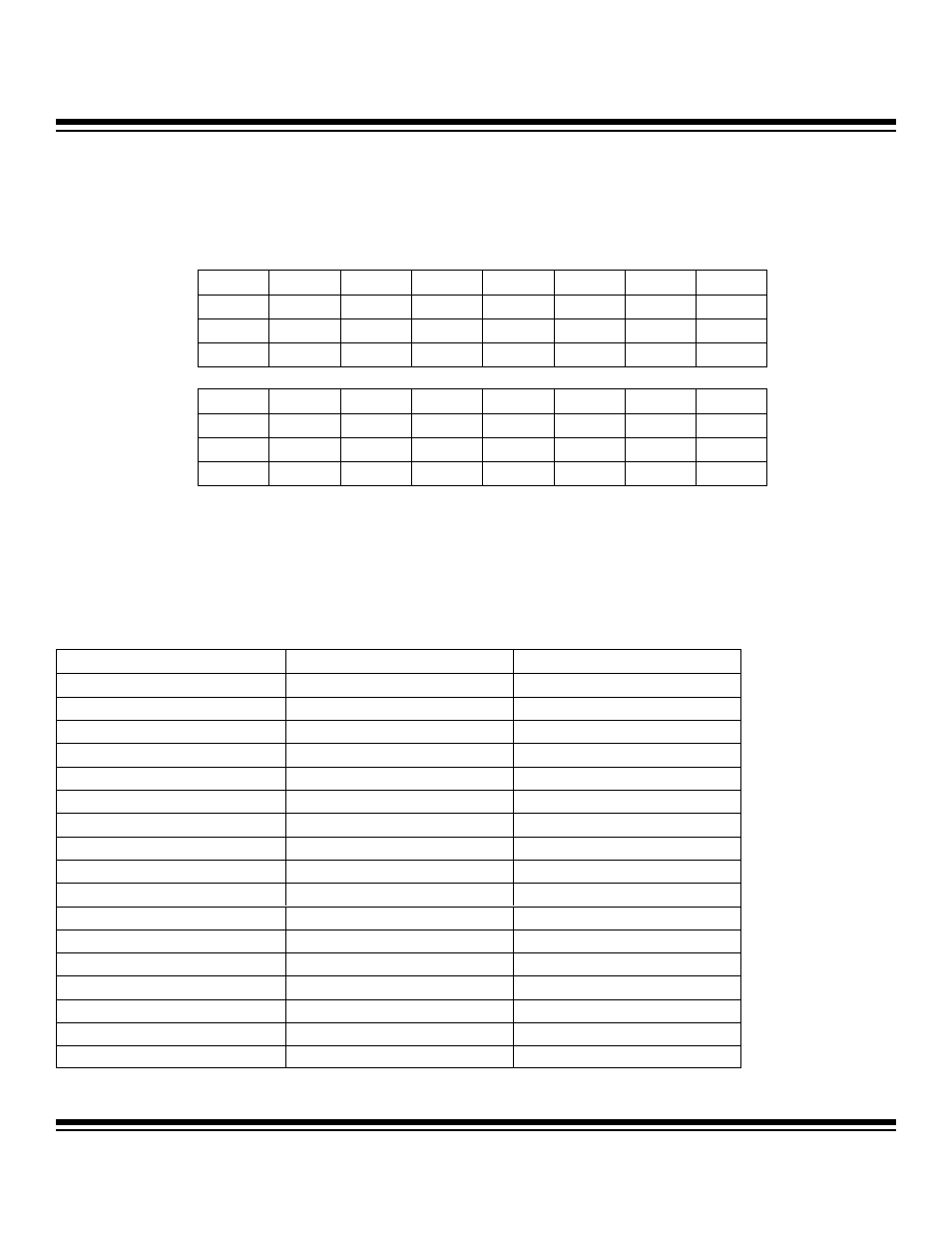
4.2.4.3 CAN 0 Interrupt Register (C0IR)
Register Description:
CAN 0 Interrupt Register
Register Name:
C0IR
Register Address:
Module 04h, Index 02h
Bits 15 to 8: Reserved. Read 0, write ignored.
Bits 7 to 0: CAN 0 Interrupt Indicator 7 to 0 (INTIN7 to INTIN0). The C0IR register provides an indication as to the status of the inter-
rupt sources in the CAN 0 processor. The contents of C0IR indicate that no interrupt is pending (00h), if an interrupt is due to a change
in the CAN 0 status register (01h), or if an interrupt has been generated from the successful reception or transmission of one of the 15
message centers (02h–10h). The C0IR register is cleared to 00h following a reset.
The following table shows the values of the INTIN7:INTIN0 bits for each interrupt source along with the respective priority of each.
Bit #
15
14
13
12
11
10
9
8
Name
— — — — — — — —
Reset
0 0 0 0 0 0 0 0
Access
r
r
r
r
r
r
r
r
Bit #
7
6
5
4
3
2
1
0
Name
INTIN7 INTIN6 INTIN5 INTIN4 INTIN3 INTIN2 INTIN1 INTIN0
Reset
0 0 0 0 0 0 0 0
Access
r
r
r
r
r
r
r
r
INTERRUPT SOURCE
INTIN7:INTIN0 HEX VALUE
INTERRUPT PRIORITY
No Pending Interrupt
00
N/A
CAN 0 Status Register
01
Highest = 1
Message 15
02
2
Message 1
03
3
Message 2
04
4
Message 3
05
5
Message 4
06
6
Message 5
07
7
Message 6
08
8
Message 7
09
9
Message 8
0A
10
Message 9
0B
11
Message 10
0C
12
Message 11
0D
13
Message 12
0E
14
Message 13
0F
15
Message 14
10
Lowest = 16
r = read
Maxim Integrated