Maxim Integrated MAXQ7666 User Manual
Page 245
MAXQ7665/MAXQ7666 User’s Guide
7-10
Bit 0: Gating Enable (G2EN). This bit enables the external Tx pin to gate the input clock to the 16-bit (T2MD = 0) or highest 8-bit
(T2MD = 1) timer. Gating uses Tx as an input, so it can only be used when T2OE0 = 0 and C/T2 = 0. Gating is not possible on the low
8-bit timer (T2Lx) when the Type 2 timer is operated in dual 8-bit mode. Gating is not supported for counter mode operation (C/T2 =
1). The G2EN bit serves a different purpose when capture and reload have been defined for both edges (CCF1:CCF0 = 11b and
CPRL2 = 1). For this special case, setting G2EN = 1 allows the T2POL0 bit to specify which edge does not cause a reload. If T2POL0
is 0, there is no reload on the falling edge; if T2POL0 is 1, there is no reload on the rising edge.
0 = gating disabled
1 = gating enabled
Note: The MAXQ7665/MAXQ7666 timer 2 does not support an input/output pin and serves only as an internal timer. Thus, gating func-
tionality does not apply for timer 2.
7.2.1.3 Type 2 Timer/Counter 2 Control Register B (T2CNBx)
Register Description:
Type 2 Timer/Counter 2 Control Register B
Register Name:
T2CNBx (x = 0, 1, 2)
Register Address:
T2CNB0: Module 02h, Index 08h
T2CNB1: Module 02h, Index 0Ch
T2CNB2: Module 03h, Index 08h
Bits 15 to 8, 6 to 4: Reserved. Read 0, write ignored.
Bit 7: Enable Type 2 Timer Low Interrupts (ET2L). This bit serves as the local enable for T2Lx interrupt sources that fall under the
TF2L and TC2L interrupt flags.
Bit 3: Type 2 Timer Overflow Flag (TF2). This flag becomes set anytime there is an overflow of the full 16-bit T2Vx timer/counter (when
T2MD = 0) or an overflow of the 8-bit T2Hx timer/counter when the dual 8-bit mode of operation is selected (T2MD = 1).
Bit 2: Type 2 Timer Low Overflow Flag (TF2L). This flag is meaningful only when in the dual 8-bit mode of operation (T2MD = 1). It
is set whenever there is an overflow of the T2Lx 8-bit timer.
Bit 1: Type 2 Timer Capture/Compare Flag (TCC2). This flag is set on any compare match between the Type 2 timer value and com-
pare register (T2Vx = T2Cx or T2Hx = T2CHx, respectively, for 16-bit and 8-bit compare modes) or when a capture event is initiated
by an external edge.
Bit 0: Type 2 Timer Low Compare Flag (TC2L). This flag is meaningful only for the dual 8-bit mode of operation (T2MD = 1). It is set
only when a compare match occurs between T2CLx and T2Lx. The Type 2 timer low does not have an associated capture function.
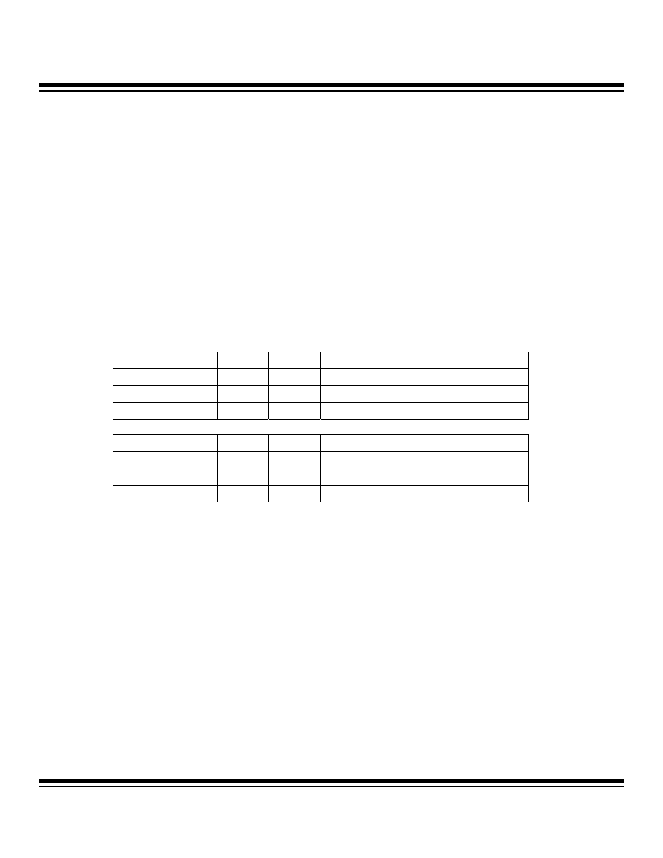
Bit #
15
14
13
12
11
10
9
8
Name — — — — — — — —
Reset 0 0 0 0 0 0 0 0
Access r r r r r r r r
Bit #
7
6
5
4
3
2
1
0
Name ET2L
— — — TF2
TF2L
TCC2
TC2L
Reset 0 0 0 0 0 0 0 0
Access rw r r r rw rw rw rw
r = read, w = write
Maxim Integrated