16 can bus activity -67, Figure 4-15. can bus activity -67, 16 can bus activity – Maxim Integrated MAXQ7666 User Manual
Page 197: 1 issues with stop mode entry while can is active
MAXQ7665/MAXQ7666 User’s Guide
4-67
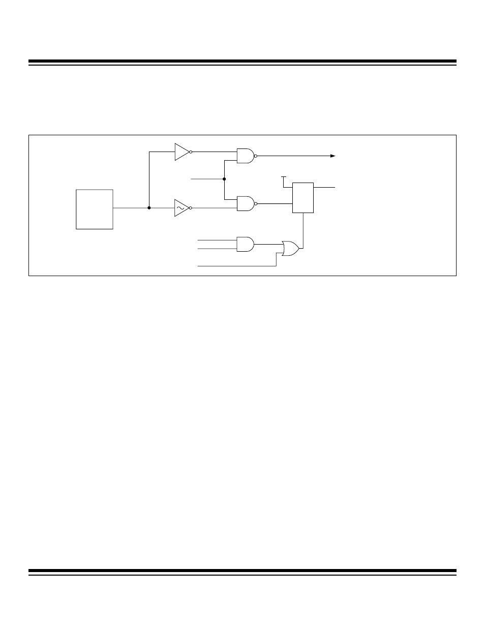
4.16 CAN Bus Activity
The CAN bus activity (CAN0BA) status is active when a CAN bus activity is detected on the CAN input pin (Figure 4-15). This signal
is used as one of the switchback sources for PMM mode or a wake-up source for stop mode if its interrupt function is also enabled.
The status bit CAN0BA in the COR register can be used by software to determine the switchback or wake-up source.
4.16.1 Issues with Stop Mode Entry While CAN is Active
When bits PDE, CRST, and SWINT are all cleared to logic 0, this condition indicates the CAN processor is active, even though this does
not mean that the CAN is actively transmitting or receiving a message. However, if the microcontroller is trying to enter stop mode while
the CAN processor is active, this could be catastrophic to the CAN network if it is actually transmitting a message.
The issue is directly related to the possibility of holding the CAN bus in dominate state when the system clock is stopped in stop mode
while the CAN is transmitting a low value. Normally, if a CAN node is in a fault state, other nodes automatically send out error frames
until the problem node takes itself offline. In this case, the problem node cannot take itself offline because it has no way to receive the
error frame or to increment the error counts without the clock.
In order to confine error to the CAN processor when it is inadvertently entering stop mode, a hardware solution is implemented:
• The TXD output is forced high by hardware, and automatically takes the CAN processor offline.
• The SWINT bit is forced to logic 1 after the stop mode is exited and 11 consecutive recessive bits on the CAN bus have been
received. Setting the SWINT bit to logic 1 inactivates the CAN processor.
• Once the SWINT bit is set, the TXD pin is released by the hardware, returning the control of the CAN bus to the CAN proces-
sor.
• The logic state of the SWINT bit also signifies the user that an error may occur and the CAN processor has been forced offline.
To activate the CAN processor, the user can clear the SWINT bit.
The following are some side effects that may not be addressed by the hardware solution.
• There is neither an error associated with this condition in the CAN status register, nor an interrupt associated with this condi-
tion. The user software should be able to determine the SWINT has been changed from 0 to 1 by hardware.
• It is possible that if a transmitted message is interrupted, it may be lost and have to be retransmitted manually. It is also possi-
ble that the message will be retransmitted automatically when the software clears SWINT if the error count is below the thresh-
old.
• The CAN error counters may have incremented due to the broken-up message and holding the bus high.
To avoid issues with stop mode entry, the user software should poll the CRST, SWINT, and PDE bits in the CAN control peripheral reg-
ister before setting the STOP bit. At least one of these bits should be set to 1 before entering stop mode. If all three bits are cleared to
0 when stop mode is entered, the CAN is taken offline and deactivated.
Figure 4-15. CAN Bus Activity
ENABLE
NOISE
FILTERING
ADDRESS
PERIPHERAL REGISTER WRITE
RESET
CAN
RECEIVER
D
V
DD
TO CAN PROCESSOR DATA INPUT
CANOBA (FOR SWITCHBACK
AND STOP-MODE REMOVAL)
C
R
Q
Maxim Integrated