4 baud-clock generator -16, Figure 6-7. uart baud-clock generator -16, 4 baud-clock generator – Maxim Integrated MAXQ7666 User Manual
Page 234
MAXQ7665/MAXQ7666 User’s Guide
6-16
6.4.4 Baud-Clock Generator
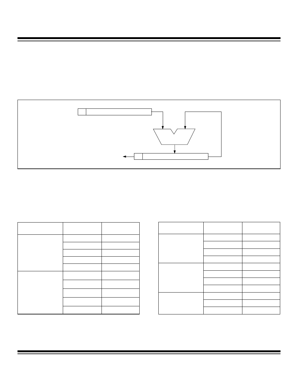
The baud-clock generator is basically a phase accumulator that produces a baud clock as the result of phase overflow from the most
significant bit of the phase shift circuitry. As illustrated in Figure 6-7, a user-programmable 16-bit phase register (PR0) is used to select
a suitable phase value for its baud clock. The phase value dictates the phase period of the accumulation process. The phase value
(from PR0) is added to the current phase accumulator value on each system clock (SMOD = 1) or every 4th system clock (SMOD =
0). The baud clock is the result of the addition overflow out of the most significant bit of the phase accumulator (bit 16). The baud-clock
generator output is always divided by 16 to produce the exact baud rate.
The following two formulas can be used to calculate the output of the baud-clock generator and the resultant mode 1, 3 baud rates.
Additionally, Table 6-4 gives example phase register (PR0) settings needed to produce some more common baud rates at certain sys-
tem clock frequencies (assuming SMOD = 1).
Baud-Clock Generator Output (BAUD) = System Clock Frequency x PR0 / 2
17
Baud Rate for Modes 1 and 3 = BAUD x 2
(SMOD x 2)
/ 2
6
Table 6-4. Example Baud-Clock Generator Settings (SMOD = 1)
Figure 6-7. UART Baud-Clock Generator
0
15
0
PR0
16
ADDITION
BAUD CLOCK OUTPUT =
CARRY OUT FROM
PHASE ACCUMULATOR [16]
0
PHASE ACCUMULATOR
SYSTEM CLOCK
FREQUENCY (MHz)
BAUD RATE
PR0 SETTINGS
115,200
75F7h
57,600
3AFBh
19,200
13A9h
9600
09D5h
8
2400
0275h
115,200
FFFFh
57,600
8000h
19,200
2AABh
9600
1555h
3.6864
2400
0555h
SYSTEM CLOCK
FREQUENCY (MHz)
BAUD RATE
PR0 SETTINGS
115,200
83D2h
19,200
2BF1h
9600
15F8h
3.579545
2400
057Eh
57,600
C000h
19,200
4000h
9600
2000h
2.4576
2400
0800h
19,200
9D49h
9600
4EA5h
1
2400
13A9h
Maxim Integrated