1 temperature sensor signals -35, 2 using the temperature sensor -35, Table 3-10. temperature sensor signals -35 – Maxim Integrated MAXQ7666 User Manual
Page 125: Table 3-10. temperature sensor signals, 1 temperature sensor signals, 2 using the temperature sensor
MAXQ7665/MAXQ7666 User’s Guide
3-35
3.4.1 Temperature Sensor Signals
The MAXQ7665/MAXQ7666 temperature sensor uses four (one external diode can be connected between AIN0/AIN1, and a second
diode between AIN2/AIN3) external signals in remote temperature sensor drive configuration as explained in Table 3-10.
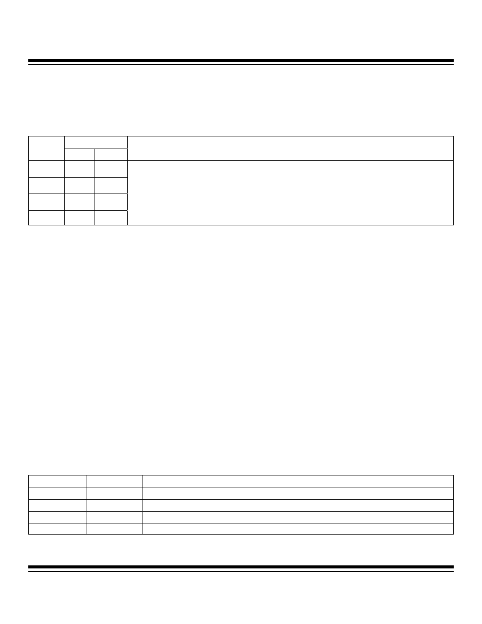
Table 3-10. Temperature Sensor Signals
The MAXQ7665/MAXQ7666 temperature sensor block works with the on-chip SAR ADC. Therefore, ensure the ADC is enabled (utility
ROM routine handles this) with the required external reference and supply. The temperature sensor has been calibrated for operation
with a +5V ADC reference level. It is possible to use other reference levels, but with diminished accuracy.
3.4.2 Using the Temperature Sensor
The following is an overview of the setup required for using the temperature sensor (internal or remote). The full details are available
as part of the utility ROM routine.
1) Temperature sensor and ADC must be enabled in the analog power enable register (APE).
2) Set up ADC configuration as follows in the ADC control register (ACNT).
ADCCS: conversion start from ADC start bit (111)
ADCDUL: single edge (0)
ADCBIP: unipolar conversion (0)
ADCDIF: single-ended or differential input (only for remote configuration)
3) Configure ADCMX4:ADCMX0 bits in the ACNT register as follows to enable/control temperature measurement.
ADCMX4: This bit must be set to configure ADC input channel for temperature measurement.
ADCMX3: Set this bit to configure temperature sensor drive current to high value. Clear this bit to configure temperature sensor
drive current to low value.
ADCMX2 and ADCMX1: These bits determine if internal or external temperature sense mode is selected. (See table below.)
ADCMX0: This bit puts the temperature sensor in auto zero state when it is set to logic 1. The autozeroing is used to cancel
internal offset effects.
Note: The above setup is not required if the temperature conversion ROM utility routine is used. All the required setup and tem-
perature measurement algorithm steps are handled in the utility routine and it returns the local or remote temperature result. The
temperature conversion utility ROM routine automatically adds the 12-bit signed offset stored in temperature offset register to
the final temperature result. See the utility ROM section (
Sections 15 and 16) for details of the routine.
PIN NUMBER
SIGNAL
48-PIN 56-PIN
FUNCTION
AIN3 13 15
AIN2 14 16
AIN1 15 17
AIN0 16 18
ADC Analog Input/Remote Temperature Sensor. Analog input pins AIN2 and AIN0 are shared with the remote
temperature sensor drive line. If the remote temperature sensor drive circuit is not selected, the pin can be used
as a differential input to the multiplexer. In differential input configuration, AIN2 is referenced to AIN3 while AIN0
is referenced to AIN1. When selected, the remote temperature sensor drive circuit supplies suitable current levels
for biasing an external diode-connected transistor to monitor temperature away from the microcontroller. The
remote temperature measurement can be made either in single-ended or differential configuration (differential
measurements are likely to be more accurate). Note, in differential configuration, AIN3 is used as the return path
for AIN2, and AIN1 is used as the return path for AIN0.
ADCMX2
ADCMX1
FUNCTION
0
0
Internal diode-connected transistor based temperature measurement
0
1
Remote diode-connected transistor based temperature measurement on AIN0
1
0
Remote diode-connected transistor based temperature measurement on AIN2
1
1
Reserved
Maxim Integrated