4 tap controller operation -6, 1 test-logic-reset -6, Figure 10-2. tap controller state diagram -6 – Maxim Integrated MAXQ7666 User Manual
Page 292: 4 tap controller operation, 1 test-logic-reset
MAXQ7665/MAXQ7666 User’s Guide
10-6
10.4 TAP Controller Operation
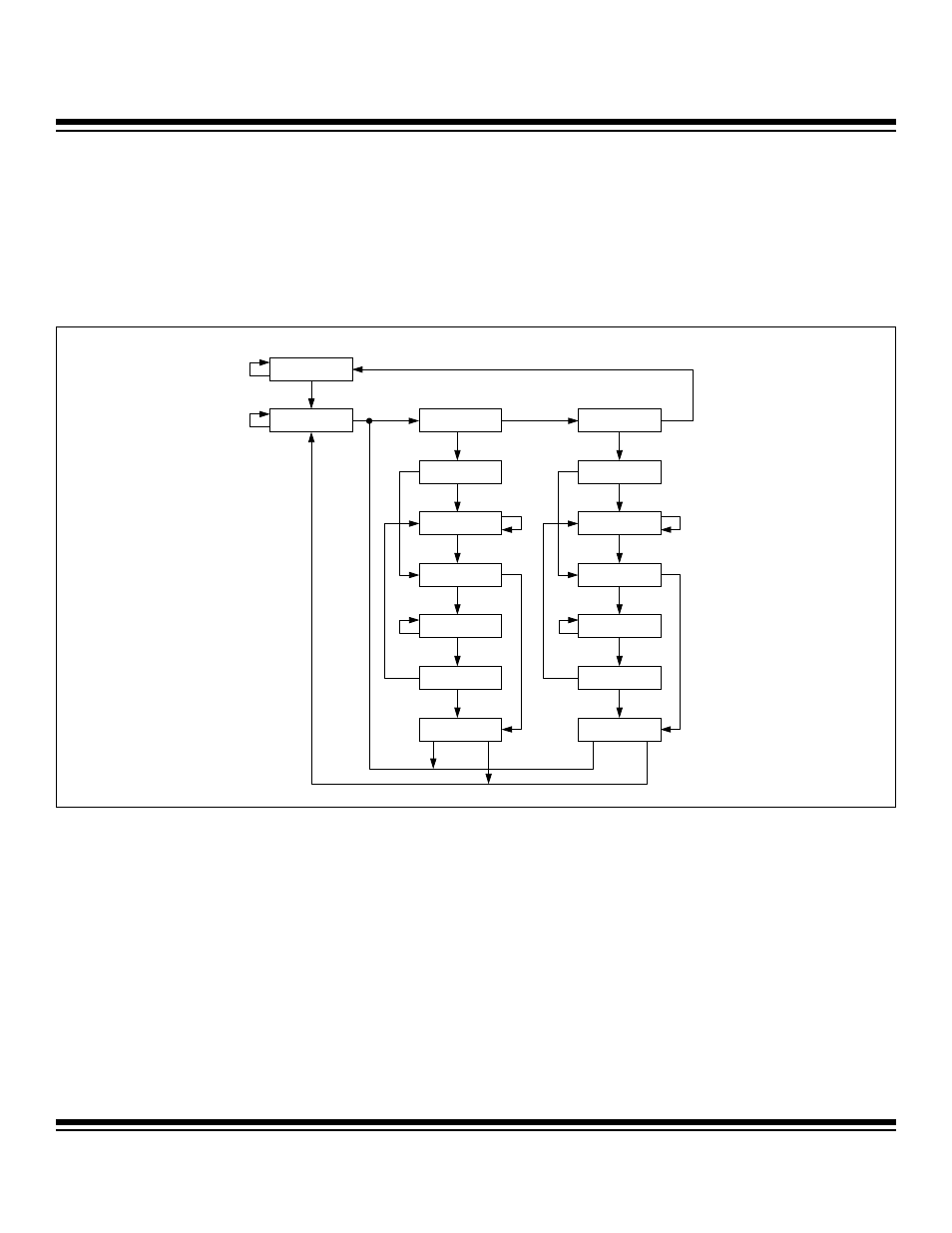
The MAXQ7665/MAXQ7666 TAP controller is formed by a finite state machine that provides 16 operational states for access control. The
TAP state control is achieved through host manipulation of the TMS and TCK signals. The TMS signal is sampled at the rising edge of TCK
and decoded by the TAP controller to control movement between the TAP states. The TDI input and TDO output are meaningful once the
TAP is in a serial shift state. This section provides a brief description of the TAP controller state machine and its state transitions.
The state diagram in Figure 10-2 summarizes the transitions caused by the TMS signal sampling on the rising edge at TCK. The TMS
signal value is shown adjacent to each state transition in the figure.
10.4.1 Test-Logic-Reset
On a power-on reset, the TAP controller is initialized to the test-logic-reset state and the instruction register (IR2:IR0) is initialized to the
bypass instruction so that it does not affect normal system operation. No matter what the state of the controller, it enters test-logic-reset
when TMS is held high for at least five rising edges of TCK. The controller remains in the test-logic-reset state if TMS remains high. An
erroneous low signal on the TMS can cause the controller to move into the run-test-idle state, but no disturbance is caused to system
operation if the TMS signal is returned and kept at the intended logic-high for three rising edges of TCK since this returns the controller
to the test-logic-reset state.
TEST-LOGIC-RESET
RUN-TEST-IDLE
SELECT-DR-SCAN
EXIT2-DR
CAPTURE-DR
SHIFT-DR
EXIT1-DR
PAUSE-DR
UPDATE-DR
SELECT-IR-SCAN
EXIT2-IR
CAPTURE-IR
SHIFT-IR
EXIT1-IR
PAUSE-IR
UPDATE-IR
1
0
1
1
1
1
1
1
1
1
1
1
1
1
1
0
0
0
0
0
0
0
0
0
0
0
0
0
1
1
0
0
Figure 10-2. TAP Controller State Diagram
Maxim Integrated