Maxim Integrated MAXQ7666 User Manual
Page 35
• XOR src (Logical XOR active accumulator with source)
• CPL (Bit-wise complement active accumulator)
• NEG (Negate active accumulator)
• SLA (Arithmetic shift left on active accumulator)
• SLA2 (Arithmetic shift left active accumulator two bit positions)
• SLA4 (Arithmetic shift left active accumulator four bit positions)
• SRA (Arithmetic shift right on active accumulator)
• SRA2 (Arithmetic shift right active accumulator two bit positions)
• SRA4 (Arithmetic shift right active accumulator four bit positions)
• RL (Rotate active accumulator left)
• RLC (Rotate active accumulator left through Carry flag)
• RR (Rotate active accumulator right)
• RRC (Rotate active accumulator right through Carry flag)
• SR (Logical shift active accumulator right)
• MOVE Acc, src (Copy data from source to active accumulator)
• MOVE dst, Acc (Copy data from active accumulator to destination)
• MOVE Acc, Acc (Recirculation of active accumulator contents)
• XCHN (Exchange nibbles within each byte of active accumulator)
• XCH (Exchange active accumulator bytes)
The active accumulator may not be the source in any instruction where it is also the implicit destination.
There is an additional notation that can be used to refer to the active accumulator for the instruction "MOVE dst, Acc." If the instruction
is instead written as "MOVE dst, A[AP]," the source value is still the active accumulator, but no AP auto-increment or auto-decrement
function will take place, even if this function is enabled. Note that the active accumulator may not be the destination for the MOVE dst,
A[AP] instruction (i.e., MOVE Acc, A[AP] is prohibited).
So, the two instructions
move A[7], Acc
move A[7], A[AP]
are equivalent, except that the first instruction triggers auto-increment/decrement (if it is enabled), while the second one will never do so.
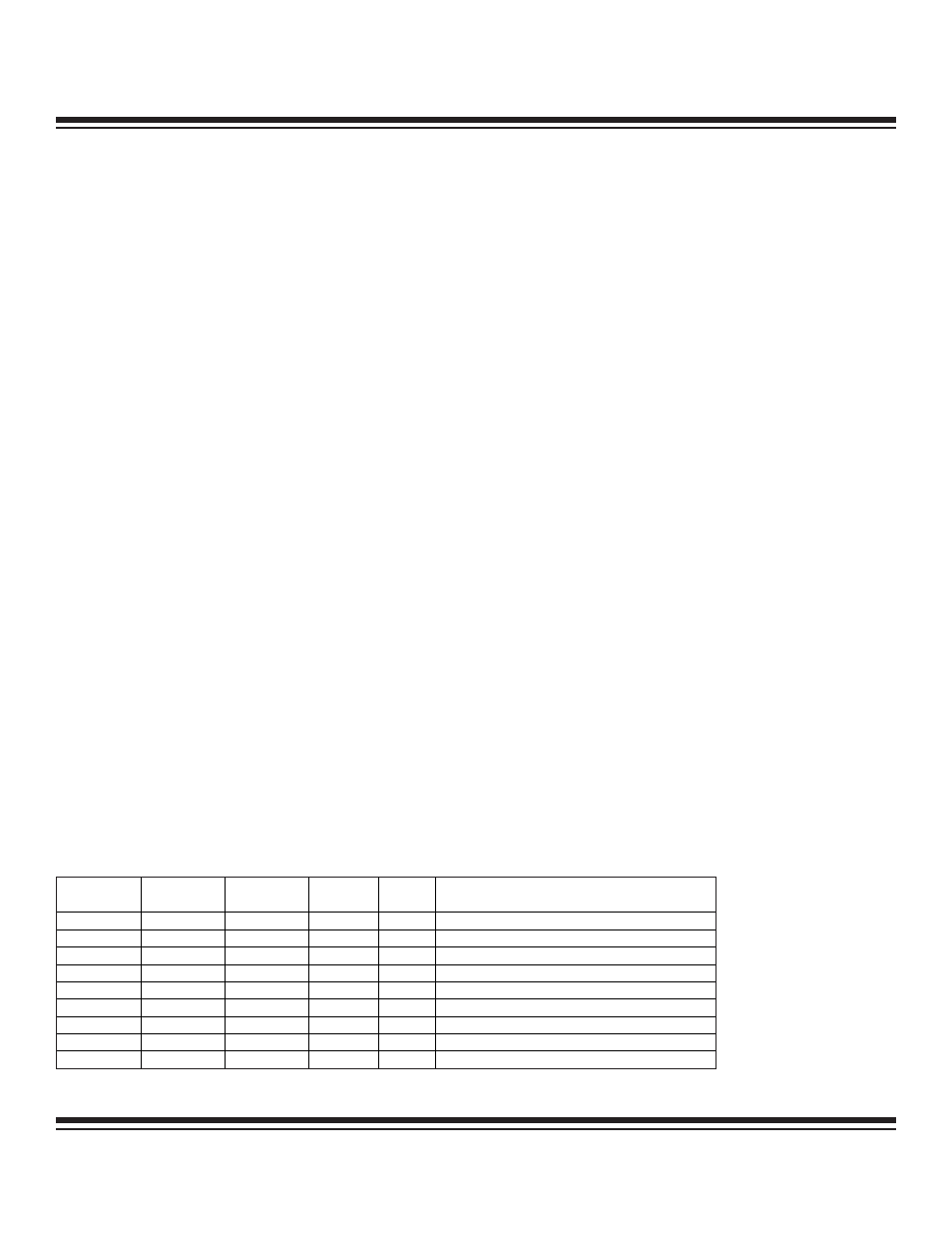
The Accumulator Pointer Control Register (APC) controls the auto-increment/decrement mode as well as selects the range of bits (mod-
ulo) in the AP register that will be incremented or decremented. There are nine different unique settings for the APC register, as listed
in Table 1-7.
Table 1-7. Accumulator Pointer Control Register Settings
MAXQ7665/MAXQ7666 User’s Guide
1-33
APC.2
(MOD2)
APC.1
(MOD1)
APC.0
(MOD0)
APC.6
(IDS)
APC AUTO-INCREMENT/DECREMENT
SETTING
0 0 0
X
00h
No
auto-increment/decrement
(default
mode)
0
0
1
0
01h
Increment bit 0 of AP (modulo 2)
0
0
1
1
41h
Decrement bit 0 of AP (modulo 2)
0
1
0
0
02h
Increment bits [1:0] of AP (modulo 4)
0
1
0
1
42h
Decrement bits [1:0] of AP (modulo 4)
0
1
1
0
03h
Increment bits [2:0] of AP (modulo 8)
0
1
1
1
43h
Decrement bits [2:0] of AP (modulo 8)
1
0
0
0
04h
Increment all 4 bits of AP (modulo 16)
1
0
0
1
44h
Decrement all 4 bits of AP (modulo 16)
Maxim Integrated