9 watchdog timer control register (wdcn) -51, 10 accumulator n register (a[n]) -51, 9 watchdog timer control register (wdcn) – Maxim Integrated MAXQ7666 User Manual
Page 53: 10 accumulator n register (a[n])
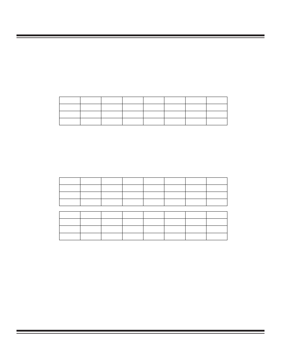
1.4.9 Watchdog Timer Control Register (WDCN)
The 8-bit WDCN register is part of the system register group and used to provide system control. It controls the watchdog timeout peri-
od and interrupt or reset generation on watchdog timeout. The watchdog timer is clocked by the internal 7.6MHz RC oscillator. See
Section 5 for a description of this register.
Register Description:
Watchdog Timer Control Register
Register Name:
WDCN
Register Address:
Module 08h, Index 0Fh
1.4.10 Accumulator n Register (A[n])
Register Description:
Accumulator n Register
Register Name:
A[n]
Register Address:
Module 09h, Index 0nh
The MAXQ7665/MAXQ7666 support 16 accumulator registers (A[0] to A[15]).
Bits 15 to 0: Accumulator n Register Bits 15 to 0 (A[n].15 to A[n].0). This register acts as the accumulator for all ALU arithmetic and
logical operations when selected by the accumulator pointer (AP). It can also be used as a general-purpose working register.
MAXQ7665/MAXQ7666 User’s Guide
1-51
Bit #
7
6
5
4
3
2
1
0
Name
POR EWDI WD1 WD0 WDIF WTRF EWT RWT
Reset
0 0 0 0 0 0 0 0
Access rw
rw
rw
rw
rw
rw
rw
rw
r = read, w = write
Note: Bits 5, 4, 3, and 0 are cleared to 0 on all forms of reset; for others, see the individual bit descriptions.
Bit #
15 14 13 12 11 10 9 8
Name
A[n].15 A[n].14 A[n].13 A[n].12 A[n].11 A[n].10 A[n].9 A[n].8
Reset
0 0 0 0 0 0 0 0
Access rw
rw
rw
rw
rw
rw
rw
rw
Bit #
7
6
5
4
3
2
1
0
Name
A[n].7 A[n].6 A[n].5 A[n].4 A[n].3 A[n].2 A[n].1 A[n].0
Reset
0 0 0 0 0 0 0 0
Access rw
rw
rw
rw
rw
rw
rw
rw
r = read, w = write
Note: This register is cleared to 0000h on all forms of reset.
Maxim Integrated