4 general can protocol-related issues -52, 1 bit stuffing -52, 2 simultaneous transmissions -52 – Maxim Integrated MAXQ7666 User Manual
Page 182: 3 transmit- and receive-error counters -52, 5 external pins -52, 4 general can protocol-related issues, 5 external pins
MAXQ7665/MAXQ7666 User’s Guide
4-52
4.4 General CAN Protocol-Related Issues
4.4.1 Bit Stuffing
The CAN processor performs a function termed bit stuffing in accordance with the CAN2.0 protocol. The bit stuffing is a mechanism
that is done on both the transmitting and receiving end of the transmission. When the CAN processor detects (in transmit or receive
mode) five consecutive bits of identical polarity, the CAN processor inserts (when transmitting) or removes (when receiving) a compli-
ment bit from the data stream. The bit stuffing is only used within the start of frame, arbitration field, control field, data field, and CRC
sequence. All other fields are unaffected. The bit stuffing in the CAN specification provides the required changes in the bus to allow
all nodes in the system to maintain synchronization.
4.4.2 Simultaneous Transmissions
The CAN processor monitors its own transmission and performs test on the outgoing data through the receive inputs. This is done to
verify that the message being sent is not in conflict with another node on the bus that may also be transmitting at the same time. If the
CAN processor detects that a transmitted recessive bit has been overwritten to the bus by a dominant bit from another node, the CAN
processor stops the transmission and waits until the next available time slot to try and retransmit the data or remote frame. This allows
the node with the higher priority to dominate the bus, without the possibility of a collision that would destroy data. The assignment of
unique identifiers to each message center within the CAN processor also establishes the natural priority of each message center with-
in the CAN processor, as well as when the message center is transmitted to the bus. Since the MSB of the identifier is transmitted first,
the message with the highest value quickly establishes the priority of which CAN unit is allowed to continue to use the bus during a
simultaneous transmission time segment. To eliminate possible problems with identical identifier, it is best that all nodes on the system
use unique identifiers. The issue of simultaneous transmission of a data frame and a remote frame with the same identifier is handled
through the use of the RTR bit. The RTR bit establishes the data frame as the higher priority to guarantee that the previously request-
ed data frame takes precedence over the newer remote frame request.
4.4.3 Transmit- and Receive-Error Counters
The CAN processor contains an 8-bit transmit-error counter and a second 8-bit receive-error counter. The CAN processor monitors both
its own transmissions as well as those of other nodes. Whenever an error condition is detected, the appropriate error counter is incre-
mented by a given value associated with the type of error detected. The MAXQ7665/MAXQ7666 CAN controller meets all the standard
error-logging conditions outlined in the CAN2.0B specification (Part B, Sept. 1991) under the heading of
Fault Confinement. Both trans-
mit- and receive-error counters can be read by the microcontroller at any time. During software initialization (SWINT = 1), the error coun-
ters can be written to establish a common value in both registers via a write capability supplied through the CAN transmit-error periph-
eral register.
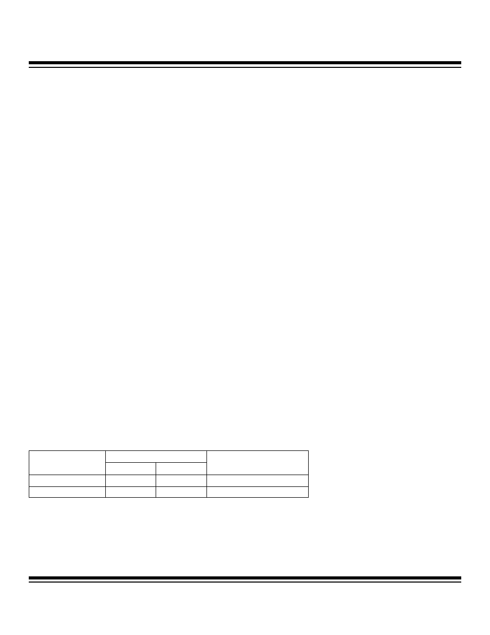
4.5 External Pins
The CAN controller uses two external signals, CANRXD and CANTXD, that are on dedicated pins. CANRXD is receive data, a digital
input that connects to a CAN transceiver output. CANTXD is transmit data, a digital output that connects to a CAN transceiver input.
The CANRXD and CANTXD signals are CAN2.0B-interface compliant with the logic level 0 (low voltage) representing a dominant state,
and logic level 1 (high voltage) representing a recessive state. The MAXQ7665/MAXQ7666 CAN controller pins are summarized in
Table 4-1.
PIN
CAN EXTERNAL
SIGNAL
48-PIN
56-PIN
DESCRIPTION
CANRXD
20
22
CAN Bus Receiver Input
CANTXD
21
24
CAN Bus Transmitter Output
Table 4-1. MAXQ7665/MAXQ7666 CAN Controller Pins
Maxim Integrated