4 watchdog timer -18, Figure 5-8. watchdog timer block diagram -18, 4 watchdog timer – Maxim Integrated MAXQ7666 User Manual
Page 215
MAXQ7665/MAXQ7666 User’s Guide
5-18
5.4 Watchdog Timer
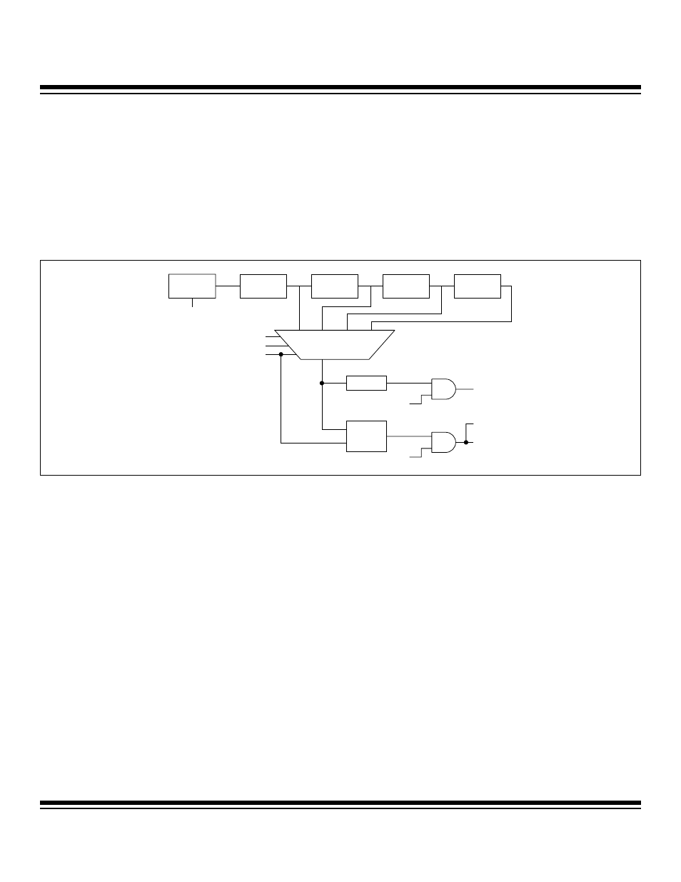
The watchdog timer is a user-programmable clock counter that can serve as a time-base generator, an event timer, or a system super-
visor. As shown in Figure 5-8, the watchdog timer is driven by the internal 7.6MHz RC clock and is supplied to a series of dividers. If
the watchdog interrupt and the watchdog reset are disabled (EWDI = 0 and EWT = 0), the watchdog timer is disabled and its input
clock is gated off. Whenever the watchdog timer is disabled, the watchdog interval timer (per WD1:WD0 bits) and 512 clock reset
counter will be reset if either the interrupt or reset function is enabled. When the watchdog timer is initially enabled, there will be a 1-
clock to 3-clock cycle delay before it starts. The divider output is selectable and determines the interval between timeouts. When the
timeout is reached, the interrupt flag WDIF is set, and if enabled, an interrupt occurs. A watchdog-reset function is also provided in
addition to the watchdog interrupt. The reset and interrupt are completely discrete functions that can be acknowledged or ignored,
together or separately for various applications.
The watchdog timer reset function works as follows. After initializing the correct timeout interval (discussed below), software can
enable, if desired, the reset function by setting the enable watchdog timer reset (EWT = WDCN.1) bit. Setting the EWT bit will
reset/restart the watchdog timer if the watchdog timer is not already enabled. At any time prior to reaching its user-selected terminal
value, software can set the refresh the watchdog timer (RWT = WDCN.0). If the watchdog timer is refreshed (RWT bit written to a logic
1) before the timeout period expires, the timer will start over. Hardware will automatically clear RWT after software sets it.
If the timeout is reached without RWT being set, hardware will generate a watchdog interrupt if the interrupt source has been enabled.
If no further action is taken to prevent a watchdog reset, in the 512 RC clock cycles following the timeout, hardware will reset the
MAXQ7665/MAXQ7666 if EWT = 1. When the reset occurs, the watchdog timer reset flag (WTRF = WDCN.2) will automatically be set
to indicate the cause of the reset; however, software must clear this bit manually after recovering from the reset.
The watchdog interrupt is also available for applications that do not need a true watchdog reset but rather a very long timer. The inter-
rupt is enabled using the enable watchdog timer interrupt (EWDI = WDCN.6) bit. When the timeout occurs, the watchdog timer sets
the WDIF bit (WDCN.3), and an interrupt occurs if the interrupt global enable (IGE = IC.0) and system interrupt mask (IMS = IMR.7)
are set and the interrupt in service (INS) bit is clear. Note that WDIF is set 512 clocks before a potential watchdog reset. The watch-
dog interrupt flag must be cleared by software.
Note: The watchdog timer is clocked by the internal 7.6MHz RC oscillator. Therefore, RCE should be set to 1 for the watchdog timer
operation. The interrupt and reset functions of the watchdog timer are summarized in Table 5-4.
Figure 5-8. Watchdog Timer Block Diagram
7.6MHz
RC CLOCK
DIVIDE
BY 2
12
2
12
2
15
2
18
2
21
DIVIDE
BY 2
3
DIVIDE
BY 2
3
WDIF
512 RC
CLOCK
DELAY
DIVIDE
BY 2
3
TIMEOUT SELECTOR
RCE
WD1
TIMEOUT
WATCHDOG
INTERRUPT
WATCHDOG
RESET
WTRF
EWDI
EWT
WD0
RWT
Maxim Integrated