Maxim Integrated MAXQ7666 User Manual
Page 120
MAXQ7665/MAXQ7666 User’s Guide
3-30
ADC DUAL-
MODE
(ADCDUL)
ADC CONVERSION
SOURCE
(ADCS2:ADCS0)
ADC CONVERSION
TRIGGER
ADC CONVERSION DESCRIPTION
000 (Timer 0)
001 (Timer 1)
010 (Timer 2)
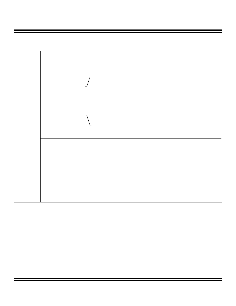
100 (ADCCNV)
Rising Edge of Conversion Source
• Sets T/H into track mode.
• ADC control logic provides the required track duration composed of power-up
delay (10 cycles), acquisition delay (3 cycles for PGA =1), and settling delay (40
cycles for PGA>1).
• If ADC is in auto shutdown, T/H placed in hold after 13 clock cycles if PGA =1
and after 93 clock cycles if PGA > 1.
• If ADC is not in auto shutdown, T/H placed in hold after 3 clock cycles if PGA =1
and after 43 cycles if PGA > 1.
• Then SAR conversion executes (13 ADC clock cycles).
101
(Inverted ADCCNV)
Falling Edge of ADCNV
• Sets T/H into track mode.
• ADC control logic provides the required track duration composed of power-up
delay (10 cycles), acquisition delay (3 cycles for PGA =1), and settling delay (40
cycles for PGA>1).
• If ADC is in auto shutdown, T/H placed in hold after 13 clock cycles if PGA =1
and after 93 clock cycles if PGA > 1.
• If ADC is not in auto shutdown, T/H placed in hold after 3 clock cycles if PGA =1
and after 43 cycles if PGA > 1.
• Then SAR conversion executes (13 ADC clock cycles).
110
(Continuous)
Write 110 to ADCS
Write 110 to ADCS
• Sets T/H into track mode.
• ADC control logic provides the required track duration.
• T/H placed in hold after 3 clock cycles if PGA =1 and after 43 clock cycles if PGA
> 1.
• Then SAR conversion executes (13 ADC clock cycles).
Conversion continuously repeated every16 or 56 ADC clock cycles.
0
(Single-Edge
Mode)
111
(Start/Busy bit)
Write 1 to Start/
Busy Bit
Write 1 to Start/Busy Bit
• Sets T/H into track mode.
• ADC control logic provides the required track duration composed of power-up
delay (10 cycles), acquisition delay (3 cycles for PGA =1), and settling delay (40
cycles for PGA > 1).
• If ADC is in auto shutdown, T/H placed in hold after 13 clock cycles if PGA =1
and after 93 clock cycles if PGA > 1.
• If ADC is not in auto shutdown, T/H placed in hold after 3 clock cycles if PGA =1
and after 43 cycles if PGA > 1.
• Then SAR conversion executes (13 ADC clock cycles).
Table 3-9. ADC Dual- and Single-Edge Modes (continued)
Maxim Integrated