1 architecture -2, Figure 8-1. type d port pin schematic -2, 1 architecture – Maxim Integrated MAXQ7666 User Manual
Page 264
SECTION 8: GENERAL-PURPOSE I/O MODULE
The MAXQ7665/MAXQ7666 smart data-acquisition microcontrollers provide 8 port pins for general-purpose I/O, which are grouped
into the logical port P0. The P0 port pins have the following features:
• All pins are multiplexed with alternate functions
• CMOS-compatible I/O levels to VDDIO and GND rails
• User-selectable, weak pullup resistors when configured as inputs (power-on state)
• Push-pull or open-drain output (can use internal pullup for open drain)
• Rising or falling edge selectable interrupt or wakeup inputs on all digital I/O pins
• Low leakage
8.1 Architecture
The MAXQ7665/MAXQ7666 support one Type D port P0. Type D is a bidirectional I/O port that incorporates Schmitt trigger receivers
and full CMOS output drivers, and can support alternate functions. The pin is either three-stated or weakly pulled up when defined as
an input. All Type D pins also have interrupt capability.
All port P0 pins can support special function (SF). Enabling the special function automatically converts the pin to that function. Special
function is usually implemented in another functional module and supported by individual enable or status bits.
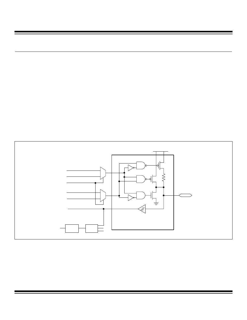
Figure 8-1 illustrates a Type D port pin function. The pin logic of each port pin is identical.
MAXQ7665/MAXQ7666 User’s Guide
8-2
Figure 8-1. Type D Port Pin Schematic
PD.x
SF ENABLE
PO.x
PI.x OR SF INPUT
SF OUTPUT
SF DIRECTION
I/O PAD
MUX
MUX
P0.x
PD
PO
˜400kΩ
VDDIO
FLAG
EIE.x
EIES.x
DETECT
CIRCUIT
INTERRUPT
FLAG
MAXQ7665/MAXQ7666
Maxim Integrated