Plot, Configuration, Plot configuration – Leica Geosystems TPS1100 Professional Series - Reference Manual User Manual
Page 51: Stakeout, Select stakeout method, continued
51
TPS1100 - Appl. Prog. Ref. Manual 2.2.0en
Stakeout
Symbols
Arrows may be used to guide the rod
person to the point to be staked.
Select the display mode of symbols
in the stakeout dialog:
• From Sta. ( )
Guidance of the rod person from the
instrument station.
• To Sta. ( )
Guidance at the rod, in relation to the
instrument station
(e.g. if working in RCS mode).
• NONE
Symbols are not used.
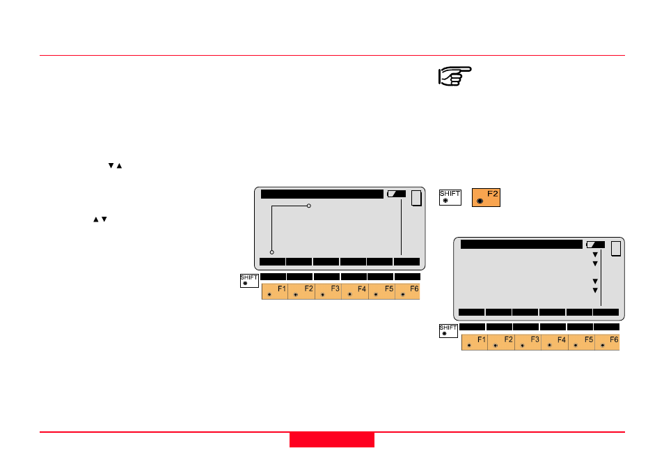
A plot is generated of the stakeout
situation with display of the stakeout
values, corresponding to the
"STAKEOUT METHOD".
Note, below a typical plot is shown
using the coordinate "STAKEOUT
METHOD".
Plot
Configuration
Depending on the
configuration that is loaded
onto your TPS1100 instrument, you
may not see some or all of the
options referred to below. See your
Leica Geosystems dealer for more
information about the configuration of
your instrument.
Start the
"Configuration Editor"
from the "SEARCH POINT" dialog.
The "Configuration Editor" sets
parameters for further program
operations:
Select Stakeout Method, continued
STAKE\
Plot
∆∆∆∆∆
E PS
∆∆∆∆∆
E : 0.024 m
∆∆∆∆∆
N : 0.012 m
∆∆∆∆∆
N
R
MC
QUIT
STAKE\
Configuration
3D Stake
:
ON
Log File
:
OFF
Log Flname:
STAKEOUT.LOG
Meas. Job :
FILE01.GSI
Data Job
:
ALNFILE0.GSI
CONT
DEFLT INFO
MC
QUIT