Road – Leica Geosystems TPS1100 Professional Series - Reference Manual User Manual
Page 214
214
TPS1100 - Appl. Prog. Ref. Manual 2.2.0en
Road+
Preparing for the example, continued
2. Copy the alignment and
template files to your PCMCIA
card. Copy the files into the GSI
subdirectory on your PCMCIA
card. If the GSI subdirectory
doesn’t already exist on the
PCMCIA card, you will need to
create it. Place the PCMCIA card
in your instrument.
3. Set up the instrument in your
work area and stakeout the
example roadway. Set the
instrument coordinates to the
values shown for point 1 (
see
figure page 206). Orient the
instrument towards a convenient
"North", and set Hz
o
to zero (
see
figure page 206). Start "ROAD+"
and continue reading this manual.
When the "Chainage & Offset"
display first appears, only the lower
portion beginning with "Station" will
be visible. To view the entire display,
use the green up/down arrow keys on
the keyboard to scroll up to the top.
Ht. Shift
Vertical shift applied to the whole
alignment. Set this to zero in this
example.
Sta. Incrm.
The station (chainage) increment set
in the configuration is displayed. If
desired, a new value can be entered.
Station
Enter the station (chainage) to be
staked.
Element
This displays the element for the
chosen station (chainage) such as
POB, PC, CURVE etc.
H. Offset
Horizontal offset to apply to the
current chainage. Set this to -0.6 to
stake the left side and 0.6 to stake
the right side of the bikeway in this
example.
V Offset
Additional vertical offset to apply to
the current chainage.
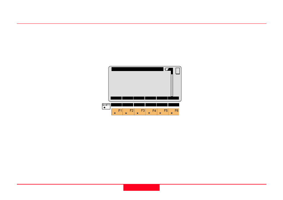
STAT |<--S S-->|
QUIT
Road+\ Station & Offset
Ht.Shift
:
0.000 m
Sta.Incrm :
1.000 m
Station
:
0.000
Element
:
POB
H Offset
:
0.000 m
V Offset
:
0.000 m
MC
CONT XSEC
<-ST ST->
STA?