Cross section assignment file, Road – Leica Geosystems TPS1100 Professional Series - Reference Manual User Manual
Page 204
204
TPS1100 - Appl. Prog. Ref. Manual 2.2.0en
Road+
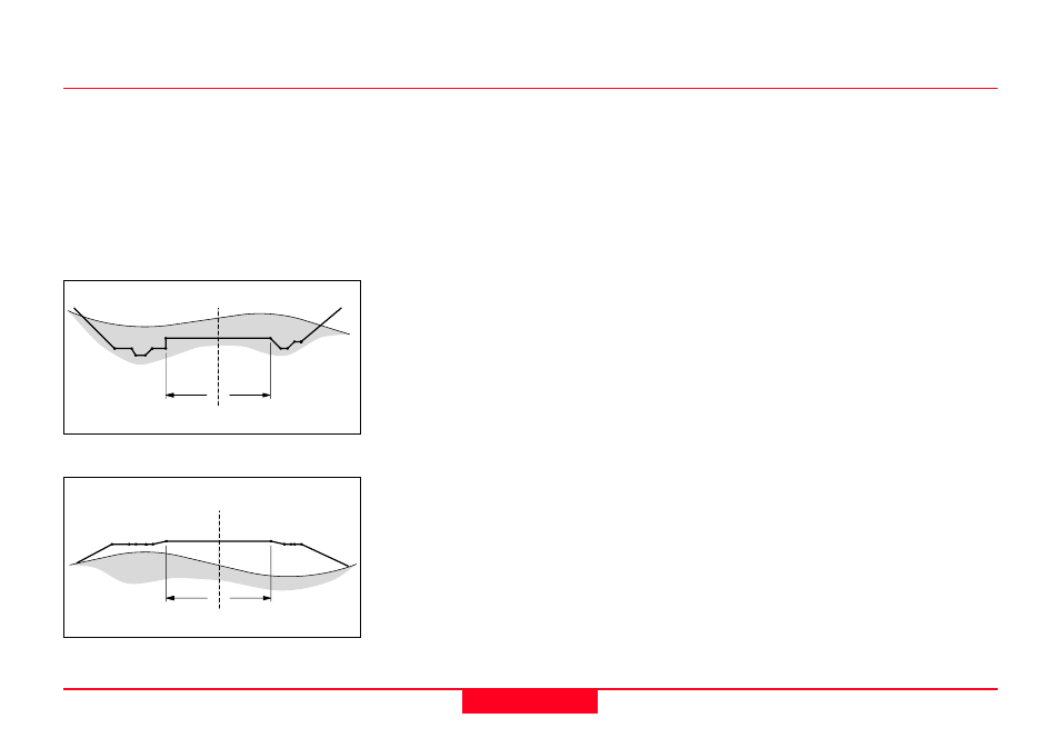
Cross Section Definition
When defining the cross section,
both a cut and fill template can be
created similar to the following
diagrams.
Cross section - Cut
Cross section - Fill
RPLUS02
RPLUS01
Positve offset
Negative offset
Positve offset
Negative offset
CL
CL
CL = Centerline
Cross Section/template File, continued
Cross Section Assignment File
The cross section assignment file
contains the following elements:
• Cross Section name
• Controlling Chainage
Road+ treats the data in the Cross
Section Assignment File in two
different ways, according to the
setting of the CRS Intrpl switch in the
configuration routine.
When CRS Intrpl is set to OFF, a
cross section assigned in this file will
remain in effect until another cross
section is defined. The transition
between the two cross sections will
be abrupt, at the station where the
next cross section assignment takes
effect. When the file is created you
will designate the name of the
template to use and the chainage to
begin using the template. The next
template name entered also contains
a starting chainage. A third template
can be assigned to begin at another
chainage and so forth.
For example, the file might contain
the following information:
XSEC1, 0
XSEC2, 100
XSEC3, 300
XSEC1, 550
Road+ would use template XSEC1
beginning at station (chainage) 0+00
and ending at station (chainage)
1+00, XSEC2 beginning at station
(chainage) 1+00 and ending at
station (chainage) 3+00, XSEC3 from
station (chainage), 3+00 to station
(chainage) 5+50, and use XSEC1
again, beginning at station (chainage)
5+50.