Insert cross section point, Road+ file editor – Leica Geosystems TPS1100 Professional Series - Reference Manual User Manual
Page 191
191
TPS1100 - Appl. Prog. Ref. Manual 2.2.0en
Road+ File Editor
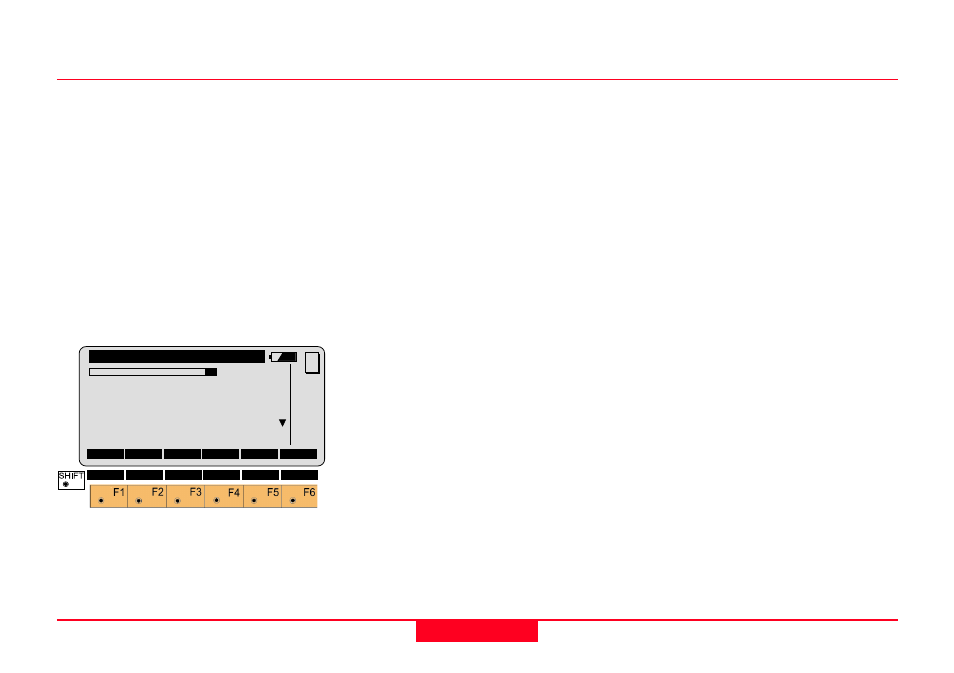
Insert Cross Section Point
You will see this dialog if you selected
"INS" on the Header Record dialog in
a Cross Section File.
The points defining a Cross Section
must be entered in sequence from
the farthest left to the farthest right on
the Cross Section. The points
defining a Cross Section should be
entered consecutively to minimize file
access during the operation of
Road+.
Template
Input the name of the template, if you
are going to create a new one or
change the name of an existing one.
Otherwise, this field displays the
name of the Template you are
currently editing.
∆∆∆∆∆
HorizDist
Input the horizontal distance from the
Horizontal Alignment to the point you
wish to create or edit.
For points to the right of the
Horizontal Alignment,
∆
HorizDist is a
positive number. For points to the left
of the Horizontal Alignment,
∆
HorizDist is a negative number.
SO Ht diff
Input the vertical distance from the
Vertical Alignment to the point you
wish to create or edit.
For points above the Vertical
Alignment, SO Ht diff is a positive
number. For points below the Vertical
Alignment, SO Ht diff is a negative
number.
Cut/Fill
(Optional) Select a description for the
current Cross Section.
• Cut means the hinge point is
below the existing surface of the
ground.
• Fill means the hinge point is
above the existing surface of the
ground.
• Standard means the hinge point is
not specifically identified as being
above or below the existing
surface of the ground (the "Cut/
Fill" and "Slope" information are
omitted from the file.)
REdit\
View/Edit File
2/ 2
Template
:
TEMPLATE
∆∆∆∆∆
HorizDist:
0.000 m
SO Ht diff:
0.000 m
Cut/Fill
:
FILL
Slope
:
0.000
INS
DONE
<--
MC
DEL
|<<- ->>| SEARC QUIT