INFICON STC-2000A Thin Film Deposition Controller Operating Manual User Manual
Page 35
p
STC-2000A DEPOSITION CONTROLLER
y
controlled by an STC-2000A output card relay connected to a pneumatic value solenoid) is moved remotely
to cover or expose the crystal surface and/or the evaporant source. The STC-2000A also has a user
programmable shutter delay. Tapped holes are provided on the sensor body for mounting the shutter
assembly and/or a mounting bracket to secure the sensor from movement. The sensor body can be opened
so that the crystal can be replaced. A "solenoid assembly" is used to provide the compressed air to the
pneumatically activated shutter and can be electrically controlled by one of the STC-2000A output relays.
There are available manual shutters activated through a feedthrough.
The sensor head has a minimum distance to the evaporant source of 10 inches to preclude being struck by
larger droplets that which in turn results in incorrect or no readings. These droplets are not part of the
evaporant stream and are therefore meaningless to the deposition process measurement. The maximum
distance is that which keeps [maintains] the crystal sensor within the evaporant stream. The crystal sensor's
deposition surface should be perpendicular to the evaporation source. The sensor mounting must not be
free to move or vibrate. If the rigidity of the pipes is not sufficient, secure the sensor with a mounting
bracket and screws into the sensor's mounting holes. The evaporant stream needs a clear path (line of sight)
to the crystal sensor's deposition surface otherwise intervening physical elements could cast a shadow in the
evaporant stream.
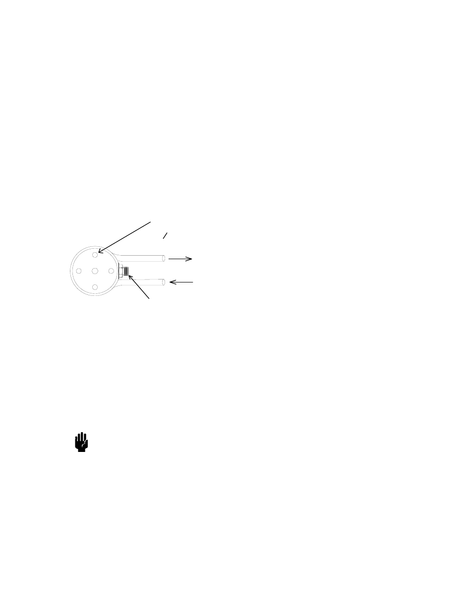
Water Cooling
Microdot Coaxial Connector
#4-40 Tap -- 4 holes
Equally Spaced
on o0.731 B.C.
The crystal sensor has a pipe bent around most of its circumference for the purpose of transferring heat
away from the crystal. Water is sent through the pipe at a specified minimum flow rate to ensure proper
cooling. The water lines are typically cut and bent to suit the needs of the chamber interior. The pipes, as
previously noted, also provide mechanical support for the sensor. Sensor pipes can be TIG welded or silver
soldered to feedthrough pipes. Swagelok compression fittings are an alternative to welding or soldering that
allow the easy connect/disconnect of pipes (the long pipes attached to the crystal sensor pass through the
Swagelok equipped feedthrough pipes). Covering the pipes and sensor cable as a group with fresh clean
aluminum (or other metal) foil helps dissipate heat from the cable thus allowing higher temperature usage
while minimizing cable movement. This also keeps deposition materials off the pipes and cable for a
cleaner environment when the foil is changed frequently.
Caution
CAUTION
Ensure that the water lines are clear of obstructions and restricting bends before
operating the sensor above room temperature.
Crystal Sensor Variations: The so called "right angle" crystal sensor has the microdot connector
emerging from the bottom flat surface along with the water cooling pipes (there are no shutter mounting
holes on this unit). The so-called "Bakeable" crystal sensor has fixed length water pipes between the
sensor body and a thick metal disc, which fits into a flange. Also between the sensor body and the thick
metal disc, is a rigid fixed length tubing that houses the electrical connection to the crystal (this allows
higher temperatures than the teflon cable of the standard configuration). The ends of the water pipes and
SECTION 2.XX
page 35 of 292