Connector installation, Connector shielding, Sensor connections – INFICON STC-2000A Thin Film Deposition Controller Operating Manual User Manual
Page 146: Stc-2000a deposition controller, Connector installation connector shielding, Figure- 4.3: recommended grounding, Connector type -- bnc
p
STC-2000A DEPOSITION CONTROLLER
y
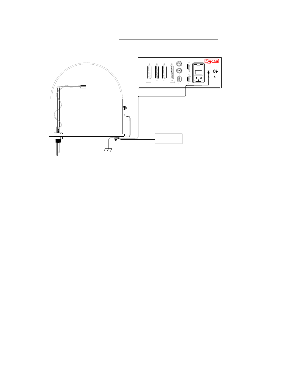
susceptible to transient noise and it is highly recommended that it be installed. Refer to
figure below for an example of proper installation.
CHAMBER
CRYSTAL SENSOR
CHAMBER GROUND
EVAPORATOR
POWER SUPPLY
WARNING
!
I/O 4 I/O 3 I/O 2 I/O 1
SENSOR
SOURCE
INPUTS / OUTPUTS
1
2
1
2
FUSE: 2 X 2.00 AMP
QUICK-ACTING (F) 250V
90-264 VAC, 50-60 Hz, 230 VA MAX
THE POWER CORD PROTECTIVE
GROUNDING CONDUCTOR MUST
BE CONNECTED TO GROUND, NO
USER SERVICEABLE PARTS
INSIDE. REFER SERVICING TO
QUALIFIED PERSONNEL
instruments
R
S
2
3
2
M
E
M
Figure- 4.3: Recommended Grounding
CONNECTOR INSTALLATION
Connector Shielding
In systems with a high electrical noise environment, attention needs to be given when wiring
connectors. A little extra time spent here can save hours of frustration later. Sycon provides mating
connectors with each instrument. For best results, use a shielded multi-conductor cable. On the D-
subminiature connectors that are supplied with the units, the metal shells each come with a set of four
grommets. Pick the grommet for the size cable you are using. After making the desired electrical
connections, remove an additional 3/4 inch of the outer insulation of the cable to expose the cable shield to
the grommet. Because the grommet is conductive, just clamping it between the metal shell is sufficient to
complete the shielding of the cable.
Figure 4.2 shows the Input/Output card card slots (labeled 1, 2, 3 and 4). The typical installation has
slot 1 filled with an input card and slot 2 filled with an output card. Figure 4.2 also shows the Sensor card
slot. The standard installation has this slot filled. The sensor card has 2 crystal inputs and 2 identical
control voltage outputs. Each of these control voltage outputs are both isolated and single ended. In a
standard STC-2000A (with 1 sensor card), the control voltage outputs may be configured such that one
output is programmed and intended as a process control voltage while the other control voltage output is
programmed and intended for use on a strip chart recorder. Back panel designations for slot 1 are: "1" and
"2" for sensors 1 and 2 in the area labeled "SENSORS" while in the area labeled "SOURCE", "1/2"
indicates source control voltages 1 and 2 on one 9 pin D-sub female. There are 4 slots for Input and/or
Output cards.
SECTION 4.5
Sensor Connections
Connector Type -- BNC
SECTION 4.XX
page 146 of 292