Analog recorder output connection/usage – INFICON STC-2000A Thin Film Deposition Controller Operating Manual User Manual
Page 148
p
STC-2000A DEPOSITION CONTROLLER
y
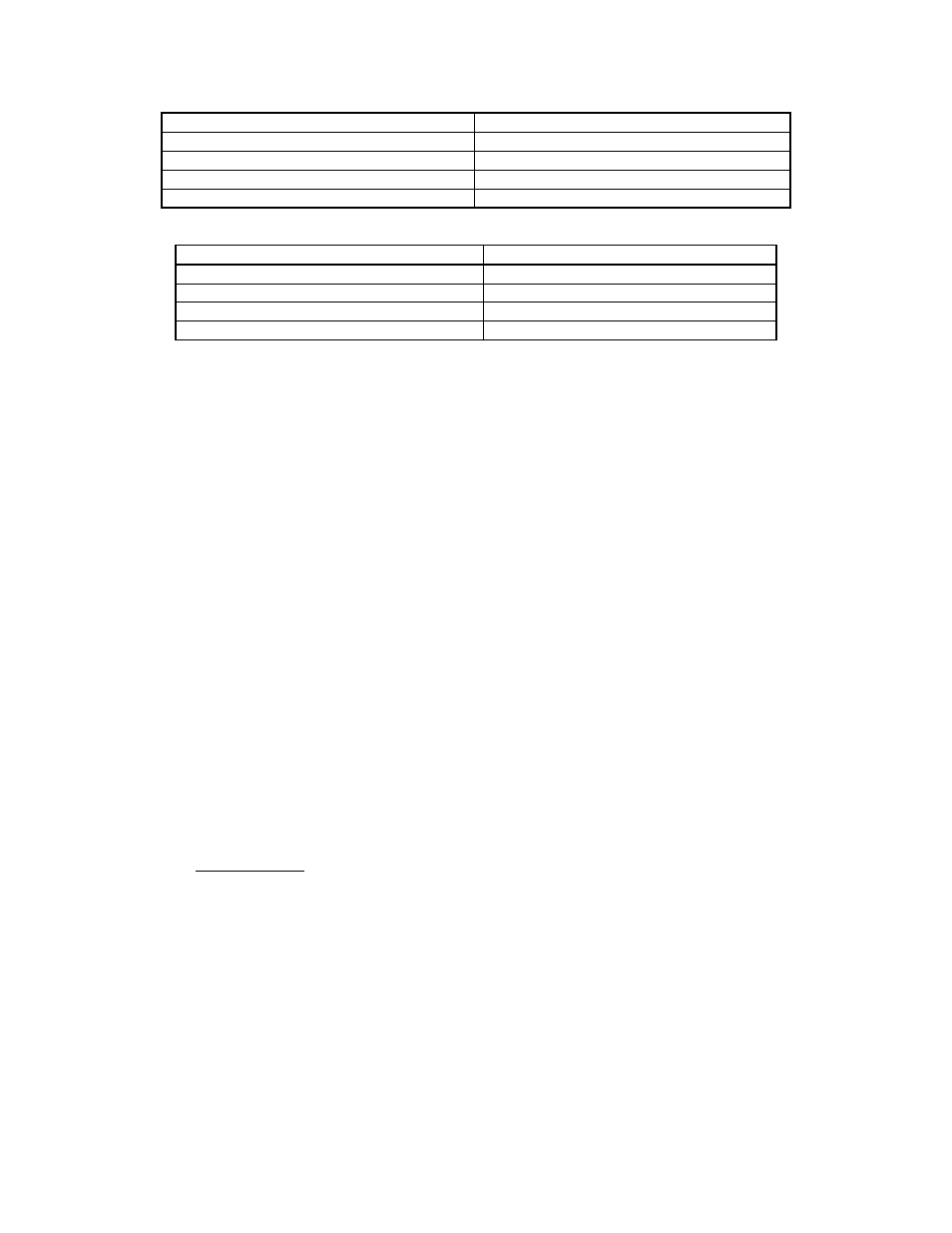
Control Signal 1
Pin No.
+Output 9
-Output 4
Analog Ground (common)
5
Shield SHLD
Connector Type – 9 PIN D-SUBMINIATURE female
Control Signal 2
Pin No.
+Output 2
-Output 6
Analog Ground (common)
1
Shield SHLD
Connector Type -- 9 PIN D-SUBMINIATURE (ON THE SAME CONNECTOR DESCRIBED ABOVE)
SECTION 4.7
Analog Recorder Output Connection/Usage
As previously discussed, the analog outputs are identical and interchangeable. One output per
STC-2000A may be used for a strip chart recorder. A standard unit having one sensor card may use the
second channel for strip chart recording as discussed here. In this example, the second output provides an
analog output voltage proportional to either displayed rate, rate deviation, power, or thickness. The channel
and status value are selected using the system configuration menu. The names of the related system
configuration menu items are recorder function and recorder output channel.
The second analog output, here described for possible use as the analog recorder output voltage,
has the connections as described above for Control Signal 2, that is pins 2, 6, 1 and shield. It is
recommended that a shielded, twisted pair cable be used to make the connection from the STC-2000A to
the chart recorder input.
Analog Recorder Output Specifications (any analog output)
Resolution
12
Bits
Accuracy
0.3 % Fs
Loading Capacity
5 mA
Full Scale Output
10 Volts
Analog Recorder Output Calibration / Interpretation
Recorder Output Types
Thickness Mode - The analog recorder output in the thickness mode is always scaled for plus or
minus 999 angstroms full-scale (9.99V). Resolution is always one (1) angstrom. Display readings above
999 angstroms will be sent to the recorder output as the remainder of the displayed value divided by 1000.
SECTION 4.XX
page 148 of 292