Operator interfaces 5-39, Function switch, Plug-in relays – WattMaster WCC II User Manual
Page 241: Port p1 and p2 low/high pressure
Section 5: Installation Guide
WCC II Operator’s Guide
Operator Interfaces
5-39
The RX light on the TUC-VR will blink when the TUC-VR is
receiving information from the SAT II-B.
The TX light will blink when the TUC-VR is transmitting data to
the SAT II-B.
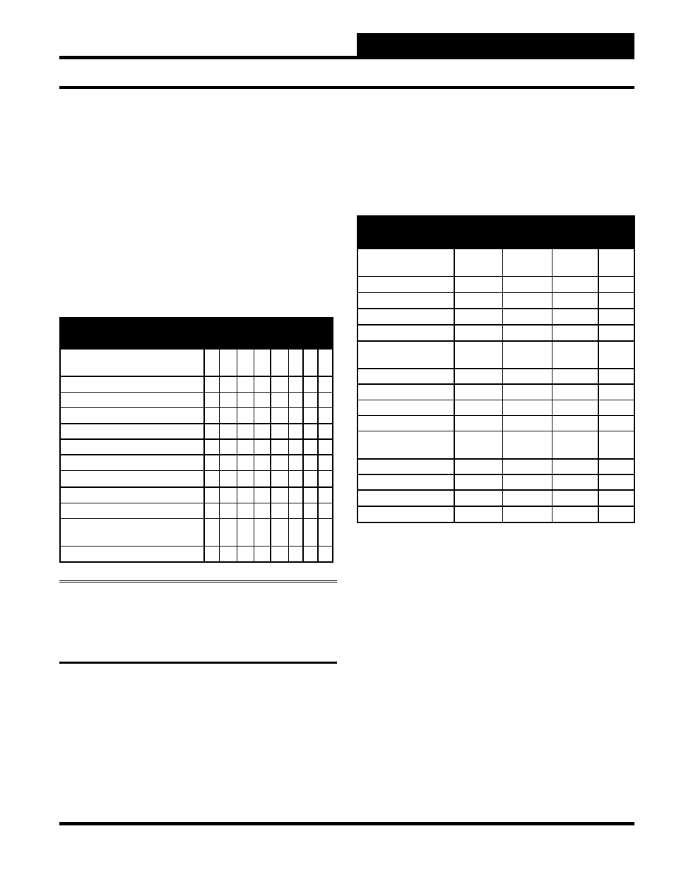
Function Switch
The TUC-VR can be used to control several types of variable air
volume (VAV) terminal units. The TUC-VR has a row of small
toggle switches labeled “FUNCTION” which must be set in the
proper position to cause the TUC-VR to control a specifi c type of
VAV terminal unit. The FUNCTION switch settings for the various
terminal units are listed below:
FUNCTION Switch Setting
1
2
3
4
5
6
7
8
Cooling Only (Factory
Confi guration)
F
F
F
F
F
F
F
Cooling/Staged Electric Reheat
F
F
F
F
F
F
F
Cooling/Timed Prop. Electric Reheat
F
F
N
N
F
F
F
Cooling/Proportional Reheat Valve
F
F
N
F
F
F
F
Parallel Fan Powered/No Reheat
F
N
F
F
F
F
F
Par Fan Pwd/Staged Elec Reheat
F
N
F
F
F
F
F
Par Fan Pwd/Time Prop Elec Reheat
F
N
N
N
F
F
F
Par Fan Pwd/Prop Reheat Valve
F
N
N
F
F
F
F
Series Fan Powered/No Reheat
F
N
F
F
N
F
F
Series Fan Pwd/Staged Elec Reheat
F
N
F
F
N
F
F
Series Fan Pwd/time Prop Elec
Reheat
F
N
N
N
N
F
F
Series Fan Pwd/Prop Reheat Valve
F
N
N
F
N
F
F
Notes:
1) F = Off, N = On 2) The TUC-VR reads the
position of the switches when it is powered up. If a change must
be made to the switches, the TUC-VR must be powered down
and then back up for the new switch settings to take effect.
Plug-In Relays
The TUC-VR can provide up to 4 contact closure outputs capable
of switching 24 volt AC or DC. A plug-in relay must be purchased
separately for each output required. The function of the relay varies
as the position of the FUNCTION switch settings on the TUC-VR
varies.
FUNCTION
Relay 1
Relay 2
Relay 3
Relay
4
VAV Box
1. Cooling Only
---
---
---
---
2. Staged Reheat
1st Stg
2nd Stg
3rd Stg
4th Stg
3. Time Prop Reheat
Heat
---
---
---
4. Prop Reheat Valve
Mod Vlve
Mod Vlve
---
---
Parallel Fan Box
5. Cooling Only
---
---
---
Fan
6. Staged Reheat
1st Stg
2nd Stg
3rd Stg
Fan
7. Time Prop Reheat
Heat
---
---
Fan
8. Prop Reheat Valve
Mod Vlve
Mod Vlve
---
Fan
Series Fan Box
9. Cooling Only
---
---
---
Fan
10. Staged Reheat
1st Stg
2nd Stg
3rd Stg
Fan
11. Time Prop Reheat
Heat
---
---
Fan
12. Prop Reheat Valve
Mod Vlve
Mod Vlve
---
Fan
Port P1 and P2 Low/High Pressure
The velocity pressure sensor is generally mounted in the inlet of the
terminal unit’s primary air duct. The TUC-VR has barbed fi ttings
for ¼ inch O.D. FRPE polyethylene tubing or ⅛ inch I.D. tygon
tubing. The maximum length of tubing allowed is 5 feet.
The low (static) pressure signal from the velocity pressure probe
is connected to port P1 on the TUC-VR, and P2 accepts the high
(total) pressure signal.