Operator interfaces 3-132 – WattMaster WCC II User Manual
Page 164
Section 3: Screen Descriptions
WCC II Operator’s Guide
Operator Interfaces
3-132
Satellite #:____
You may enter the satellite number of the SAT II-A at this location.
The ECC/WCC II system “looks” at each SAT II-A as four SAT II
controllers with up to 8 TUC’s connected to each SAT II controller.
Therefore, each SAT II-A has 32 TUC’s associated with it
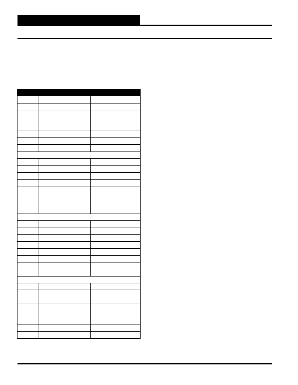
Satellite Number
TUC Summary Screen
TUC #1
SAT II-A Base Number
U1
TUC #2
SAT II-A Base Number
U2
TUC #3
SAT II-A Base Number
U3
TUC #4
SAT II-A Base Number
U4
TUC #5
SAT II-A Base Number
U5
TUC #6
SAT II-A Base Number
U6
TUC #7
SAT II-A Base Number
U7
TUC #8
SAT II-A Base Number
U8
TUC #9
SAT II-A Base Number +1
U1
TUC #10
SAT II-A Base Number +1
U2
TUC #11
SAT II-A Base Number +1
U3
TUC #12
SAT II-A Base Number +1
U4
TUC #13
SAT II-A Base Number +1
U5
TUC #14
SAT II-A Base Number +1
U6
TUC #15
SAT II-A Base Number +1
U7
TUC #16
SAT II-A Base Number +1
U8
TUC #17
SAT II-A Base Number +2
U1
TUC #18
SAT II-A Base Number +2
U2
TUC #19
SAT II-A Base Number +2
U3
TUC #20
SAT II-A Base Number +2
U4
TUC #21
SAT II-A Base Number +2
U5
TUC #22
SAT II-A Base Number +2
U6
TUC #23
SAT II-A Base Number +2
U7
TUC #24
SAT II-A Base Number +2
U8
TUC #25
SAT II-A Base Number +3
U1
TUC #26
SAT II-A Base Number +3
U2
TUC #27
SAT II-A Base Number +3
U3
TUC #28
SAT II-A Base Number +3
U4
TUC #29
SAT II-A Base Number +3
U5
TUC #30
SAT II-A Base Number +3
U6
TUC #31
SAT II-A Base Number +3
U7
TUC #32
SAT II-A Base Number +3
U8
For example, assume that the SAT II-A is named #4 and you would
like to set up the screen for TUC #20. TUC #20 would be seen as
U4 on satellite #6. From the table, the satellite number for TUC
#20 is the base number plus 2. Since the SAT II-A is named 4, the
base number is 4.
SAT II-A base number = 4
SAT II-A base number +2 = 6
TUC #20 = U4
Therefore, TUC 20 is seen as U4 on satellite controller 6.
Description:
The description message which is entered on the TUC Set-Up
Screen is displayed here to help you identify the different TUC’s
within the system.
Mode:
The mode is automatically displayed by the system showing the
version of the TUC. For example, if you have a TUC-AR which
has an actuator driver and relay outputs, then the mode would be
A&R.
Current Setpoint:
The value that the TUC is currently using as its setpoint, as entered
on the EA Driver Screen, is displayed here. A message will also
appear indicating if the value is the “Day” (ON schedule) or
“Night” (OFF schedule) setpoint.
Status:
A message may appear here to indicate if the TUC is using either
the alternate setpoint or if it is operating in the reverse action
(morning warm-up) mode.
Binary Status
BIN 1 BIN 2
CL
OP
The ON or OFF status of the TUC binary inputs are displayed here.
OP stands for OPEN or OFF, and CL stands for CLOSED or ON.
BIN1 and BIN2 may have remote switches connected to them. A
CL message means that the remote switch is CLOSED, and an OP
message means that the remote switch is OPEN.
BIN 1 (Tenant Override)
OP: The remote switch is OPEN, which means the
tenant override mode is NOT active.
CL: The remote switch is CLOSED, which means the
tenant override mode is ACTIVE.