Operator interfaces 5-24 temperature sensors – WattMaster WCC II User Manual
Page 226
Section 5: Installation Guide
WCC II Operator’s Guide
Operator Interfaces
5-24
Temperature Sensors
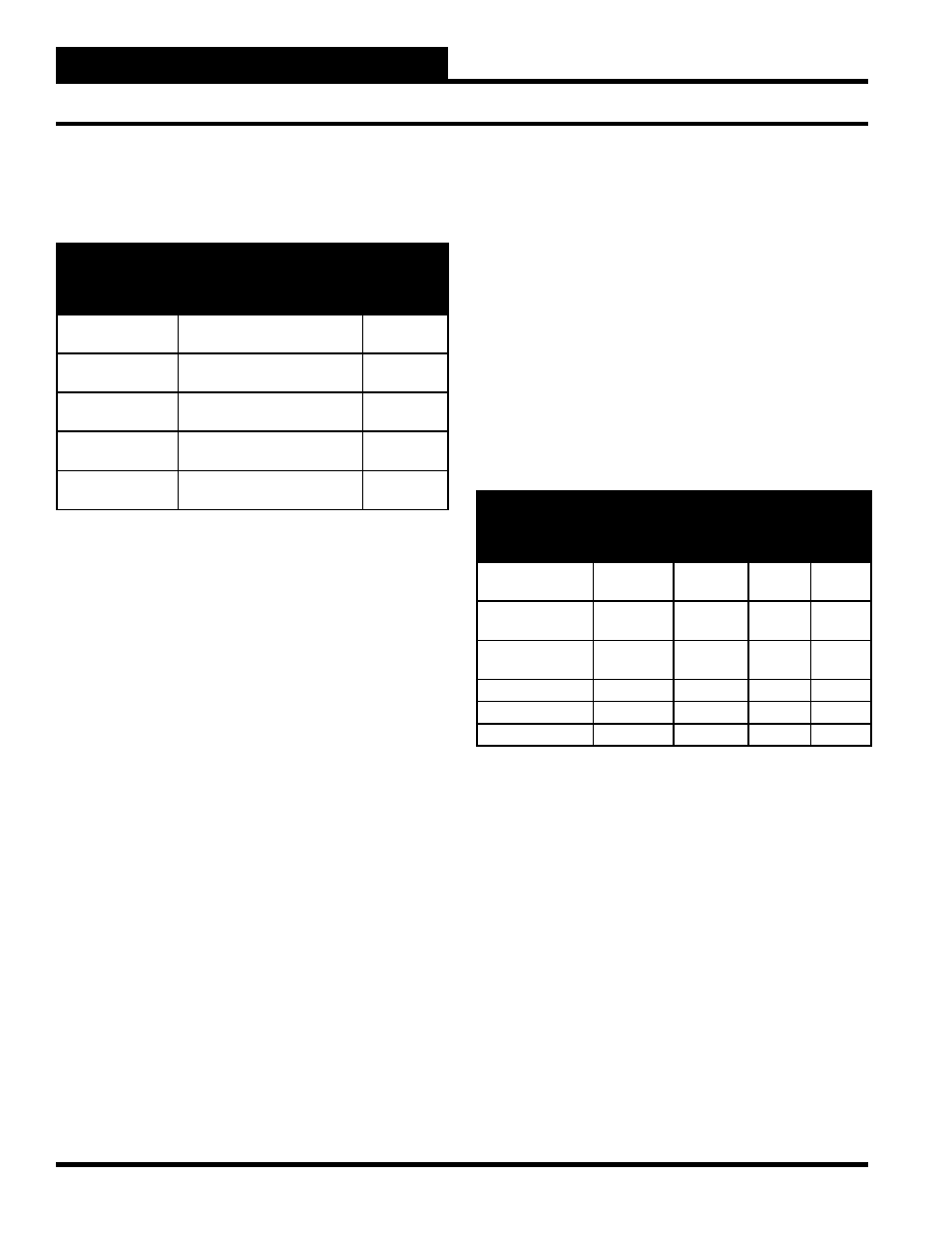
Temperature Industries offers the following temperature sensors to
be used with the ECC/WCC II system.
SENSOR
DESCRIPTION
CONTROL
RANGE
(°F)
ETS-1/WRS-1
2-Wire, Surface Mounted Rm
Temp Sensor
40 - 90
ETC-1F/WRS-1F
2-Wire, Flush Mounted Rm
Temp Sensor
40 - 90
ETS-2F/WRS-1F3
3-Wire, Flush Mounted Rm
Temp Sensor
40 - 90
ETS-3/WDS-1
2-Wire, Air/Water Temp Sensor
30 - 120
or 40 - 240
ETS-4/WOS-1
2-Wire, Outdoor Air Temp
Sensor
-20 - 150
2-Wire Sensors
The “+V” terminal on the SAT II controller is a 12 VDC power
source. The temperature sensor is a current transducer which
transmits a current proportional to the temperature it is sensing.
The load resistor on the front of the SAT II controller is in series
with the temperature sensor and connects the “ATI” terminal to the
“GND” terminal. The ECC/WCC II system monitors the voltage
between the “ATI” terminal and “GND” on the SAT II controller
to determine the temperature sensed by the sensor. The system
is designed for 1 VDC between “ATI” and “GND” to represent
the 100% scale value on the Analog Input Screen, and 0 VDC
represents the 0% scale value. The maximum allowable voltage
across the load resistor is 1.2 volts.
The specifi cations of the temperature sensor determine the value
of the SAT II load resistor and the 0% and 100% scale value on the
Analog Input Screen. The load resistors must be ordered separately
and fi eld installed. 10 resistors come in one package.
The air/water temperature sensor is used to monitor the temperature
of the air in duct work or the temperature of fl uid in a pipe. For fl uid
pipe applications, the probe may be removed from the transmitter,
strapped to the pipe, and thermally insulated from the ambient air,
and the transmitter mounted remotely by extending the two wires
connecting the probe to the transmitter. The transmitter may be
located up to 100 feet from the probe, or the sensor may be mounted
in an immersion well with the use of thermal compound to insure
good thermal conduction between the water and the sensor. For
chilled water sensing, it is highly recommended that the sensing
element be removed from the transmitter (control head) to prevent
condensation in the head.
The air/water sensor has two temperature ranges available,
depending on which load resistor is used. A 100 ohm load resistor
gives the sensor a control range of 30-120 °F, and a 50 ohm load
resistor gives the sensor a control range of 40-240 °F.
3-Wire Temperature Sensor
The 3-wire temperature sensor accomplishes the same thing as the
2-wire sensor, only you can think of the resistor being in the sensor
and not at the satellite controller. The 3-wire sensor is wired to
the “+V,” “ATI,” and “GND” terminals on the SAT II controller.
The 3-wire sensor transmits a voltage between “ATI” and “GND”
which corresponds to temperature, and therefore, a resistor at the
SAT II controller is not required.
The following table shows the required load resistor and the values
for the Analog Input Screen.
TEMPERATURE
SENSOR
LOAD
RESISTOR
(Ohms)
DATA
PATTERN
0%
SCALE
100%
SCALE
2-Wire Surface
Mount
100
XXX.X
0.0
100.0
2-Wire Flush
Mount
301
XXX.X
0.0
100.0
3-Wire Flush
Mount
None
XXX.X
0.0
100.0
Air/Water
100
XXX.X
0.0
100.0
Air/Water
50
XXX.X
0.0
200.0
Outdoor Air
50
XXX.X
-50.0
150.0
4-20 MA Sensors
Sensors that provide 4-20 mA signals can be used with the SAT
II controllers. The SAT II controllers are designed to have 1 VDC
across the load resistors at full scale and 0 VDC across the load
resistors at 0% scale. Since the load resistors have 20 mA through
them at full scale, and 1 VDC is required across the load resistor, a
4-20 mA sensor requires a 50 ohm load resistor.
V
1 Volt
R = --------- = -------------- = 50 Ohms
I
0.020 Amps
When programming the Analog Input Screen for a 4-20 mA
sensor, the 100% scale value is the value represented when the
sensor sends 20 mA to the SAT II controller, and the 0% scale
value is the value represented when the sensor sends 0 mA to the
SAT II controller. For example, consider a 4-20 mA sensor which
measures duct static pressure.The sensor provides 4 mA when the
duct static pressure is 0 inches of water column and 20 mA when