Operator interfaces 3-137 – WattMaster WCC II User Manual
Page 169
Section 3: Screen Descriptions
WCC II Operator’s Guide
Operator Interfaces
3-137
-------Binary
Output Options----------
Relay 1
Choice
1. Forced ON if Relay 2 is ON:
[Yes]
[No]
2. Forced ON if Relay 3 is ON:
[Yes] [No]
3. Forced OFF during MWU cycle:
[Yes] [No]
4. [Normal]
[Forced ON if BIN 2 is closed]
[Runs only if BIN 2 is closed]
[Forced ON if BIN 2 is closed (day)]
5. Forced ON day, Cycle night]
[cycle day and night)]
Relay 2
1. Disable if BIN 2 is closed:
[Yes]
[No]
2. Disable during MWU cycle:
[Yes]
[No]
3. [ON] [OFF] if [GB__] is ON:
Relay 3
1. Disable if BIN 2 is closed:
[Yes]
[No]
2. Disable during MWU cycle:
[Yes] [No]
3. [ON] [OFF] if [GB__] is ON:
The relays on the TUC can be automatically forced ON or OFF to
obtain the desired control scheme for many applications.
BIN2
The TUC has a binary input labeled “BIN2.” A remote dry contact
closure may be wired between the “BIN2” and “GND” terminals
on the TUC. When the remote switch is closed, the TUC “sees”
BIN2 as being ON.
MWU
“MWU” stands for Morning Warm-Up. The TUC “sees” MWU as
being ON when the Reverse Action mode on the EA Driver Screen
for this particular TUC is enabled.
GB
The TUC can monitor the ON/OFF status of 15 global binary
values. Only GB1-15 are recognized by the TUC’s.
Binary Input Mode:
[Normal]
[Forced OFF during day]
[Forced OFF during night]
[Forced ON during day]
[Forced ON during night]
Override Control is
[Normal]
[One shot retriggerable]
[One shot with warning blip]
And the active time period is [0-255] [Seconds]
[Minutes]
A remote mounted tenant override switch can be wired to binary
input 1 (BIN 1) to allow the TUC to control according to its ON
schedule (Day) mode setpoints while the switch is closed or for a
programmable amount of time after a momentary switch has been
closed. When the remote mounted dry contact closure connected
between BIN1 and GND is closed, the ECC/WCC II “sees” the
appropriate binary input (Ln) for the specifi c satellite as being
ON.
When SAT II controllers are used with the ECC/WCC II system,
the binary inputs are called L1-L16. Since one SAT II-A is viewed
as four SAT II controllers, the binary input values of a SAT II-A are
seen as the binary inputs of four SAT II controllers.
For example, if a SAT II-A is named #4, then it will appear as
satellite number 4, 5, 6 and 7 on the ECC/WCC II system screens.
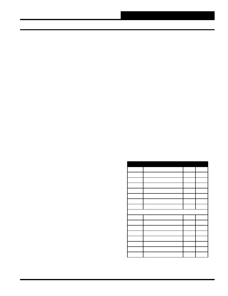
The following table shows how the TUC’s will appear to the ECC/
WCC II system. For example, BIN1 and BIN2 on TUC #20 will
be seen at the ECC/WCC II Operator Control Console as binary
inputs L4 and L12 on satellite controller #6.
Satellite Number
BIN 1
BIN 2
TUC #1
SAT II-A Base Number
L1
L9
TUC #2
SAT II-A Base Number
L2
L10
TUC #3
SAT II-A Base Number
L3
L11
TUC #4
SAT II-A Base Number
L4
L12
TUC #5
SAT II-A Base Number
L5
L13
TUC #6
SAT II-A Base Number
L6
L14
TUC #7
SAT II-A Base Number
L7
L15
TUC #8
SAT II-A Base Number
L8
L16
TUC #9
SAT II-A Base Number +1
L1
L9
TUC #10
SAT II-A Base Number +1
L2
L10
TUC #11
SAT II-A Base Number +1
L3
L11
TUC #12
SAT II-A Base Number +1
L4
L12
TUC #13
SAT II-A Base Number +1
L5
L13
TUC #14
SAT II-A Base Number +1
L6
L14
TUC #15
SAT II-A Base Number +1
L7
L15
TUC #16
SAT II-A Base Number +1
L8
L16