Analog outputs – WattMaster WCC II User Manual
Page 15
Section 1: General Instructions
WCC II Operator’s Guide
Operator Interfaces
1-5
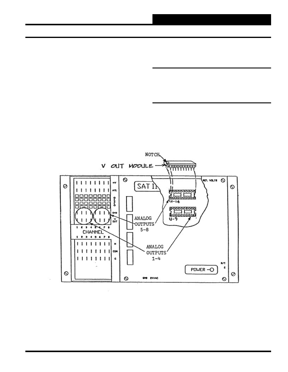
Analog Outputs
An analog output is a variable DC voltage signal sent from the
satellite controller used for proportional control of devices with
modulating actuators. The analog outputs are wired to the “V-Out”
and “Gnd” terminals on the SAT II controller and are named P1-
P8. The P stands for Proportional Output.
The SAT II controller has the capability of providing 8 analog
output signals which have a maximum range of 0-15 VDC. If the
analog outputs are to be used, V-Out modules must be purchased
and are fi eld installed. One V-Out module is required for 4 analog
outputs, and two V-Out modules can be installed in one satellite
controller to allow one satellite controller to provide up to eight
analog outputs.
Each analog output has a limit of 15 mA. The total current output
of all 8 analog outputs must be kept under 115 mA.
Note:
Later versions of the satellite controllers require two
modules for each set of four analog outputs. On these models,
sockets U-9 and U-10 activate outputs 1-4, and sockets U-11
and U-14 activate outputs 5-8.