WattMaster WCC II User Manual
Page 227
Section 5: Installation Guide
WCC II Operator’s Guide
Operator Interfaces
5-25
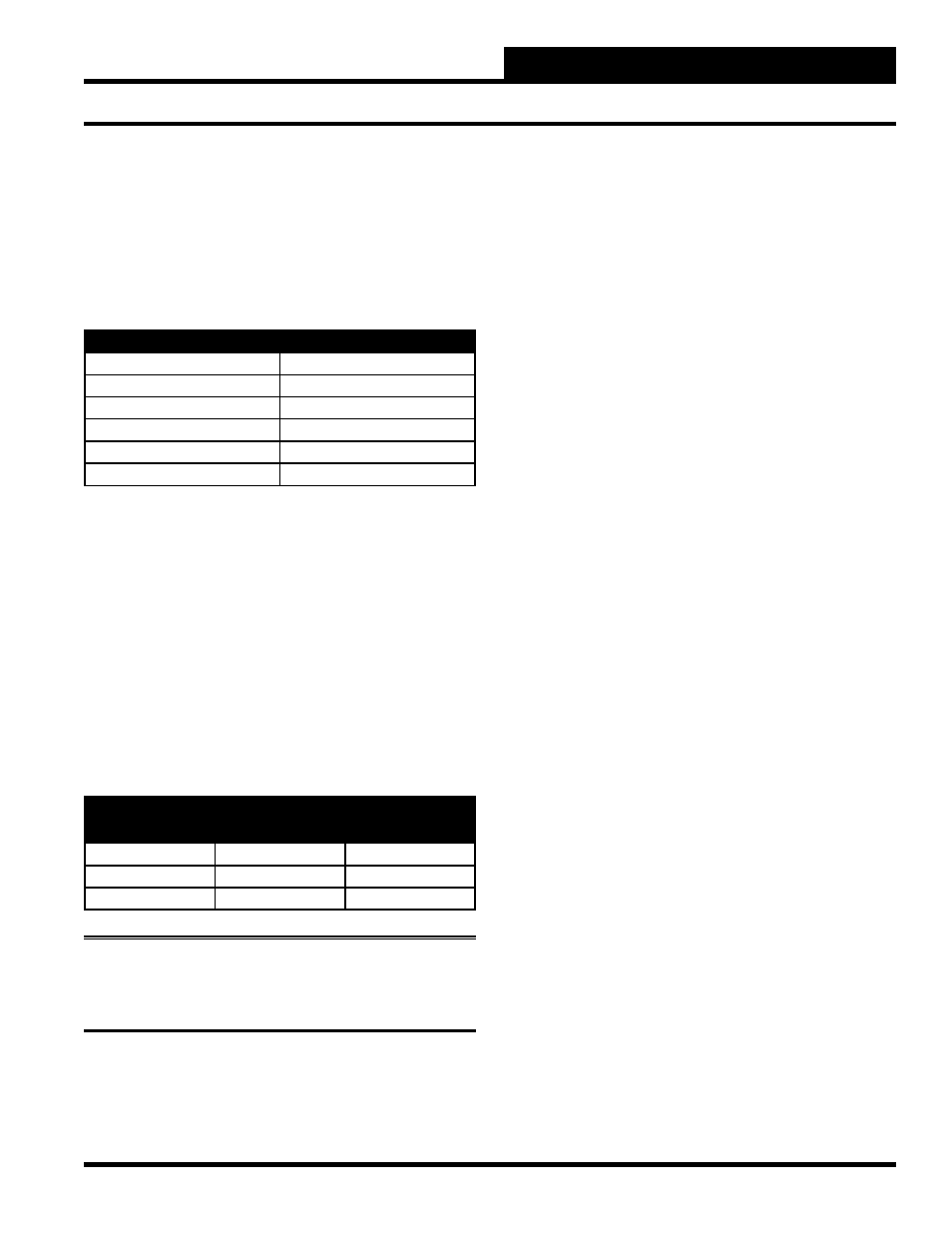
the duct pressure is 2 inches of water column. The 100% scale
value on the Analog Input Screen is 2.00” W.C., and the 0% scale
value is -0.50” W.C.
The full scale value is fairly straightforward and easy to understand.
The 0% scale value on the other hand is a bit more complicated.
The following table shows the signal out of the sensor versus the
duct static pressure.
Signal from Sensor (mA)
Duct Static Pressure
20
2.00” W.C.
16
1.50” W.C.
12
1.00” W.C.
8
0.50” W.C.
4
0.00” W.C.
0
-0.50” W.C.
When programming the Analog Input Screen, the 0% scale value
is the value when 0 mA are supplied by the sensor. Since 0 mA
represent -0.50” W.C., -0.50” W.C. is input for the 0% scale
value.
0 - 1, 0 - 5 and 0 - 1- VDC Sensors
The SAT II can accept a 0-1, 0-5, or a 0-10 VDC signal from a
sensor. Since the SAT II is designed for 1 VDC across the load
resistor to represent the full scale value of the analog input, the
voltage from the 0-10 and 0-5 VDC sensors needs to be reduced
before it reaches the SAT II controller. This is accomplished by
placing a line resistor in the circuit in addition to the load resistor.
The following table shows the recommended value of the line and
load resistor to be used.
SIGNAL FROM
SENSOR
LINE RESISTOR
(Ohms)
LOAD RESISTOR
(Ohms)
0 - 10 VDC
9000
1000
0-5 VDC
4000
1000
0-1 VDC
None
10000
Note:
Check the manufacturer’s specifi cations to determine
if a ground wire needs to be connected from the sensor to the
“GND” terminal on the SAT II controller.