WattMaster WCC II User Manual
Page 230
Section 5: Installation Guide
WCC II Operator’s Guide
Operator Interfaces
5-28
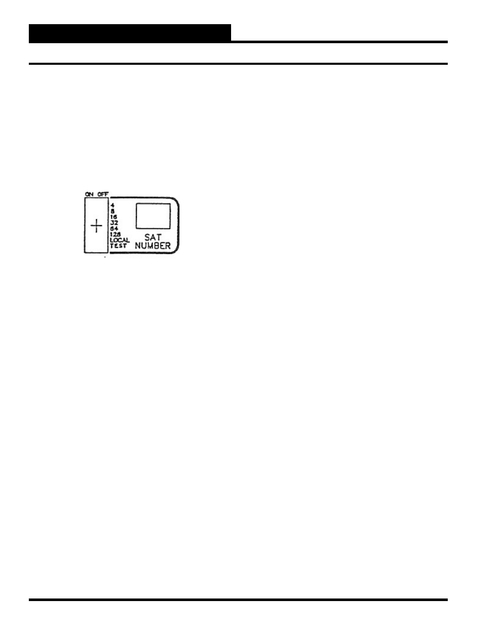
Addressing the SAT II-A
There can be up to 60 SAT II-A’s connected together on a 2-wire
communication loop. In order for the ECC/WCC II system to
communicate properly with each SAT II-A, each SAT II-A must be
assigned a separate number (address). The number is assigned by
positioning the small toggle switches on the front of the SAT II-A
in the proper position. The toggle switches are housed together in
a block as shown below:
When the switch is in the ON position, it represents the number on
the right in the drawing. That is, when switch 4 is ON and all of the
other switches are off, the SAT II-A is addressed (named) #4. The
switches are additive. That is to say, when switches 4 and 8 are ON,
and all of the other switches are OFF, the SAT II-A is addressed
#12. The SAT II-A looks at the position of the switch setting during
its power-up cycle. If you need to readdress a SAT II-A, you must
change the switch settings, turn off the power to the SAT II-A, and
then turn the SAT II-A back on again.
When the LOCAL switch is in the ON position, the TUC’s will
operate according to their “local set” setpoints. That is, the TUC’s
will operate as if the front end computer is off-line, but the SAT
II-A is still present.
The test mode is active if the TEST switch is in the ON position.
The word “TEST” can be input as the binary value on the EA
Driver Screen to select the alternate setpoints. When you want
to check the operation of the alternate setpoints, place the TEST
switch in the ON position.