WattMaster WCC II User Manual
Page 217
Section 5: Installation Guide
WCC II Operator’s Guide
Operator Interfaces
5-15
SAT II Chip Switches
The standard SAT II controller is capable of providing 16 binary
(on/off) outputs. The SAT II controllers are modular in design,
and therefore, if binary outputs are not required, the chip switches
which allow the SAT II to provide binary outputs do not have to be
purchased. Each binary output requires 1 chip switch which must
be purchased separately and fi eld installed. Chip switches come in
packages of 8.
The terminals for the binary outputs are found at the lower left
hand corner of the SAT II controller and are labeled H, COM, and
C. The chip switches can be thought of as the electronic equivalent
of a relay which can make or break a 24 VAC circuit between the
COM to H or COM to C terminals. The COM to H contacts are
referred to as K1h-K8h, and the COM to C contacts are referred to
as K1c-K8c. K stands for contact, and the numbers 1-8 stand for
the channel on the SAT II controller.
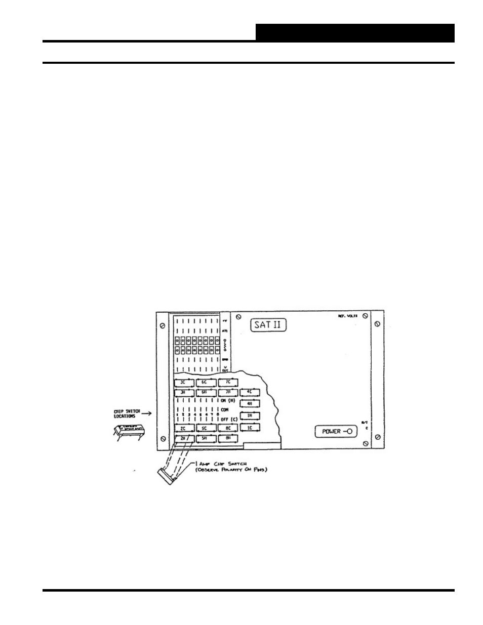
The chip switch location for each binary output is shown below.
The chip switch serving the COM to H contact on channel 1 is
labeled “1H,” etc.
Notice that the distance between the legs on the chip switch are
different to insure that the chip switches are not installed backwards.
The chip switches must be installed carefully, making sure not to
bend the metal legs. To install the chip switches, insert the bottom
legs part-way into the IC socket, and then insert the top legs part-
way. Check to make sure all of the legs are started properly and
then gently push down on the chip until it is fi rmly in place.