WattMaster WCC II User Manual
Page 185
Section 3: Screen Descriptions
WCC II Operator’s Guide
Operator Interfaces
3-153
If the SAT II-B is named #4 and you would like to set-up the
screens for TUC-VR #20, you should access Analog Input Screen
#4, Control Output Screen #4, and TUC-VR Set-Up Screen #4 on
satellite #6.
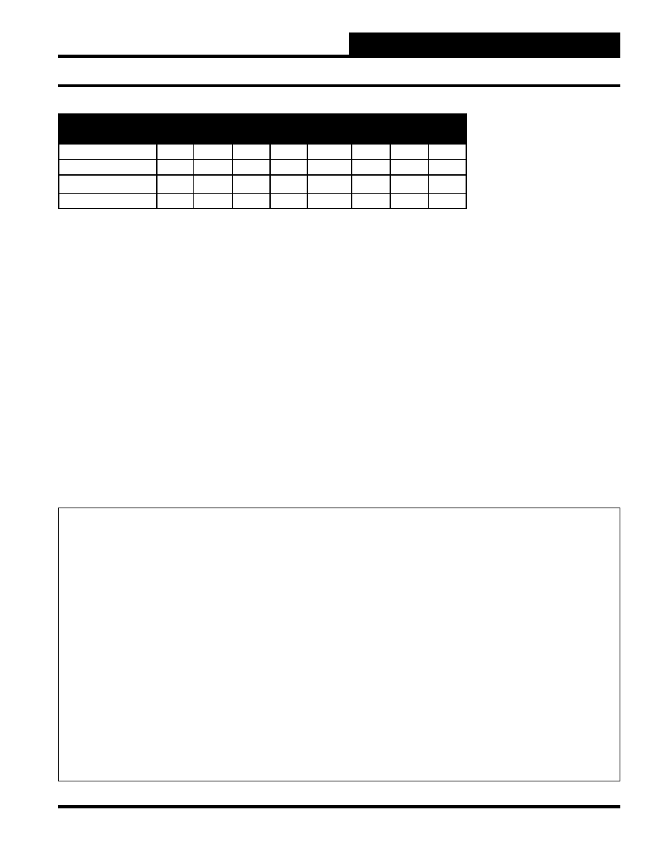
Velocity Reset # 1
This input designates the Velocity Reset Screen (1-8) you would
like to edit. (See table above.)
Mode:
[Cooling/Electric]
[Cooling/Hot
Water]
[Fan/Electric]
[Fan/Hot
Water]
[Induct./Electric]
[Induct./Hot
Water]
The mode is automatically displayed on the TUC-VR Screen. The
mode is determined by the “FUNCTION” switch settings on the
TUC-VR.
SAT II-B #4
Velocity Reset #
SAT II B #
1
2
3
4
5
6
7
8
4 (Base Number)
TUC1
TUC2
TUC3
TUC4
TUC5
TUC6
TUC7
TUC8
5 (Base Number+1)
TUC9
TUC10
TUC11
TUC12
TUC13
TUC14
TUC15
TUC16
6 (Base Number+2)
TUC17 TUC18
TUC19
TUC20
TUC21
TUC22
TUC23
TUC24
7 (Base Number+3)
TUC25 TUC26
TUC27
TUC28
TUC29
TUC30
TUC31
TUC32
FUNCTION
Switches
1 2 3 4 5 6 7 8
Cooling Only (Factory Confi guration)
F F F F F F F F
Cooling/Staged Electric Reheat
F F F F F F F F
Cooling/Timed Prop. Electric Reheat
F F F F F F F F
Cooling/Proportional Reheat Valve
F F F F F F F F
Parallel Fan Powered/No Reheat
F F F F F F F F
Par Fan Pwd/Staged Elec Reheat
F F F F F F F F
Par Fan Pwd/Time Prop Elec Reheat
F F F F F F F F
Par Fan Pwd/Prop Reheat Valve
F F F F F F F F
Series Fan Powered/No Reheat
F F F F F F F F
Series Fan Pwd/Staged Elec Reheat
F F F F F F F F
Series Fan Pwd/Time Prop Elec Reheat
F F F F F F F F
Series Fan Pwd/Prop Reheat Valve
F F F F F F F F
Notes: 1) F = Off, N = On 2) The TUC-VR reads the position of the switches when it is powered up. If a change must be
made to the switches, the TUC-VR must be powered down and then back up for the new switch settings to take effect.