WattMaster WCC II User Manual
Page 218
Section 5: Installation Guide
WCC II Operator’s Guide
Operator Interfaces
5-16
SAT II V-Out (DAC) Modules
The SAT II controller has the capability of providing 8 analog
output signals which have a maximum range of 0-15 VDC. The
SAT II controllers are modular in design, and therefore, if analog
outputs are not required, the V-out modules do not have to be
purchased. If the analog outputs are required, 1 V-out module is
required for 4 analog outputs, and 2 V-out modules can be installed
in one SAT II controller to allow 1 SAT II controller to provide up
to 8 analog outputs. The V-out modules must be ordered separately
and are usually fi eld installed.
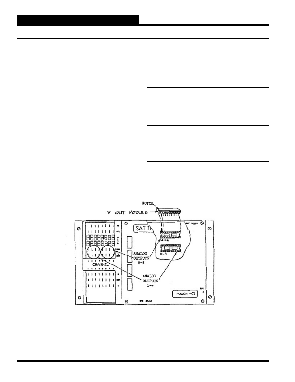
The V-out modules are installed in the sockets labeled “U9” and
“U14” as shown below. The V-Out module in the “U9” location
serves analog outputs 1-4. The V-out module in the “U14” location
serves analog outputs 5-8.
Each V-out module has a notch on one end which needs to be
nearest the left end of the SAT II controller as you are facing the
SAT II controller as shown below.
WARNING:
The V-out module will be destroyed if it is
installed backwards, so care should be taken to make sure the
module is installed properly before the SAT II controller is
powered up.
To install the V-out modules, carefully insert the bottom legs part-
way into the IC socket and then insert the top legs part-way. Check
to make sure all of the legs are started properly and then gently
push down until the module is fi rmly in place.
Note:
Later versions of the satellite controllers require two
modules for each set of four analog outputs. On these models,
sockets U-9 and U-10 activate outputs 1-4, and U-11 and U-14
activate outputs 5-8.