WattMaster WCC II User Manual
Page 187

Section 3: Screen Descriptions
WCC II Operator’s Guide
Operator Interfaces
3-155
Auxiliary Fan Setpoint (Parallel): 30%
If the TUC-VR is confi gured to control a parallel fan powered
terminal unit, relay #4 on the TUC-VR is used to run the fan. When
the space requires heating, the primary air damper begins to close
to reduce the amount of cold air supplied to the space. When the air
fl ow through the terminal unit falls below the setpoint, the TUC-
VR will energize relay #4 and run the fan.
Auxiliary Reheat Offset
The heating setpoint is determined by subtracting the reheat offset
value from the space temperature setpoint entered on the EA Driver
Screen for this TUC-VR. For example, if the space temperature
setpoint is 74 °F, and the offset is 4 °F, the heating setpoint is
70 °F.
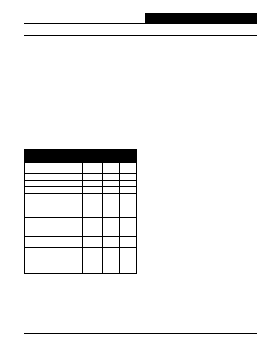
TUC-VR may use one or all of relays 1-4 for heating depending on
how the TUC-VR FUNCTION switches are set.
FUNCTION
Relay 1
Relay 2
Relay 3
Relay 4
VAV Box
1. Cooling Only
---
---
---
---
2. Staged Reheat
1st Stg
2nd Stg
3rd Stg
4th Stg
3. Time Prop Reheat
Heat
---
---
---
4. Prop Reheat Valve
Mod Vlve
Mod Vlve
---
---
Parallel Fan Box
5. Cooling Only
---
---
---
Fan
6. Staged Reheat
1st Stg
2nd Stg
3rd Stg
Fan
7. Time Prop Reheat
Heat
---
---
Fan
8. Prop Reheat Valve
Mod Vlve
Mod Vlve
---
Fan
Series Fan Box
9. Cooling Only
---
---
---
Fan
10. Staged Reheat
1st Stg
2nd Stg
3rd Stg
Fan
11. Time Prop Reheat
Heat
---
---
Fan
12. Prop Reheat Valve
Mod Vlve
Mod Vlve
---
Fan
Data reg. A: [Current duct temperature]
[Current air fl ow]
[Hot water valve position]
[Space temp - temp setpoint]
[Space temp - duct temp]
[% of maximum air fl ow rate]
Data reg. B: [Current duct temperature]
[Current air fl ow]
[Hot water valve position]
[Space temp - temp setpoint]
[Space temp - duct temp]
[% of maximum air fl ow rate]
Several values associated with the TUC-VR are stored in a “data
register” and are available for monitoring and/or they can be used
as inputs on other ECC/WCC II Screens. The data registers are in
the form of “RnA” and “RnB.”
“R”
stands for Data Register.
“n”
is the number of the TUC-VR Screen of the data
register.
“A”&“B”
are the two data registers available for each screen.
Each data register (“RnA” and “RnB”) can take on the value of one
of the following items:
[Current
duct
temperature]
[Current air fl ow]
[Hot water valve position]
[Space temp - temp setpoint]
[Space temp - duct temp]
[% of maximum air fl ow rate]
To make your selection, move the cursor over this input and press
the
until the desired choice appears; then press
.
An example of using a data register would be to set up an Analog
Trend Screen to record the value of the air fl ow through the TUC-
VR terminal unit at fi ve minute intervals. Assume the TUC-VR is
“named” #1 and is connected to SAT II-B #4. Select “current air
fl ow” as the value for data register A. Now move to the Analog
Trend Log Screen for satellite #4 and set up the screen to record the
value of “R1A” every fi ve minutes.
Data reg. C (AO):
[Current duct temperature]
[Current air fl ow]
[Hot water valve position]
[Space temp - temp setpoint]
[Space temp - duct temp]
[% of maximum air fl ow rate]
Data register C is accessed in a different manner from data registers
A and B. Data register may be thought of as the “Analog Output”
signal from the TUC-VR Screen. The “Analog Output” values
associated with the TUC-VR are available for monitoring and/or
