Recommended data entry procedure, Analog inputs – WattMaster WCC II User Manual
Page 13
Section 1: General Instructions
WCC II Operator’s Guide
Operator Interfaces
1-3
Recommended Data Entry Procedure
When setting up an ECC/WCC II system, the screens can be
programmed in any order. However, you may fi nd it easier to
follow this sequence:
Make back-up copies of the disks
System Parameter Screen
Utility Screen - Rebuild Satellite Tables
Satellite Summary Screen
On/Off Units Messages Screen / Alarm Message
Screen —Enter the On/Off messages, units of
measure messages, and alarm messages, and then
print the messages using
. Keep a
copy of these messages handy while entering data
on the remaining screens
Week Schedule Screens
Holiday Screen
Analog Input Screens
Logic Switch Screens
Control Output Screens
TUC Screens
Analog Output Screens
Analog Global Screens
Binary Global Screens
Optimal Start Screens
Shed/Restore Screens
Duty Cycle Screens
Proportional Reset Screens
Energy Consumption Screens
Trend Log Screens
Custom Screens/Enhanced Graphic Screens
Special Keys Programs
Save Satellite Data to Disk
Make Back-Up Copies of the Disks
1.
2.
3.
4.
5.
6.
7.
8.
9.
10.
11.
12.
13.
14.
15.
16.
17.
18.
19.
20.
21.
22.
23.
24.
Analog Inputs
An analog input is a numerical value (signal) sent to the SAT II
controller to allow monitoring of space temperatures, duct pressures
etc. The SAT II controller can accept 8 analog inputs which
are named, A1-A8. (Note: A1-8 may be either analog or binary
inputs.) On certain screens (such as Global Analog Screens), you
must indicate the satellite controller number along with the channel
on the satellite controller. For example, 12A2 means analog input
number 2 on satellite controller #12.
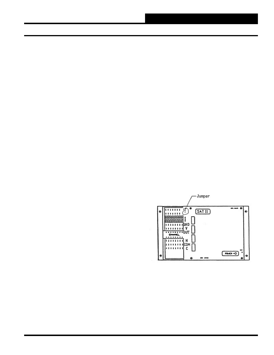
The analog inputs are usually wired to the “+V” and “ATI” (Actual
Temperature In) terminals on the SAT II controller (three wire
sensors are wired to the “GND” terminal also.) The “+V” terminal
on channels 1-7 are a 12 VDC power source. The “+V” terminal
on channel 8 provides either 12 VDC or 18 VDC depending on
the position of the jumper under the cover near channel 8. To get
12 VDC from the “+V” terminal on channel 8, the jumper must
connect the A and B terminals. To get 18 VDC, the jumper must
connect the B and C terminals.
A 20 mA sensor can be used on up to 5 channels on the SAT II
controller. The total current for all 8 analog inputs must be kept
under 115 mA.