Point addresses, Operator interfaces 1-7, Table of point addresses – WattMaster WCC II User Manual
Page 17: Constant point addresses
Section 1: General Instructions
WCC II Operator’s Guide
Operator Interfaces
1-7
Point Addresses
A Point Address uniquely identifi es a point within the ECC/WCC
II system. All point addresses have an associated “analog” or
“binary” value. The term “analog” simply means a value which
is represented by a number (such as room temperature, duct static
pressure, etc.). The term “binary” means the value is represented by
one of two conditions, ON or OFF. An input is a signal sent to the
ECC/WCC II system, and an output is sent from the ECC/WCC II
system. Therefore, room temperature is an analog input, fan status
is a binary input, and controlling a fan relay is a binary output.
In addition to the inputs and outputs that are wired to the SAT
II controllers, there are several software point addresses within
the system. For example, the ECC/WCC II system has 32 week
schedules. This means that a separate day/night schedule can be
assigned to 32 different areas of the building.
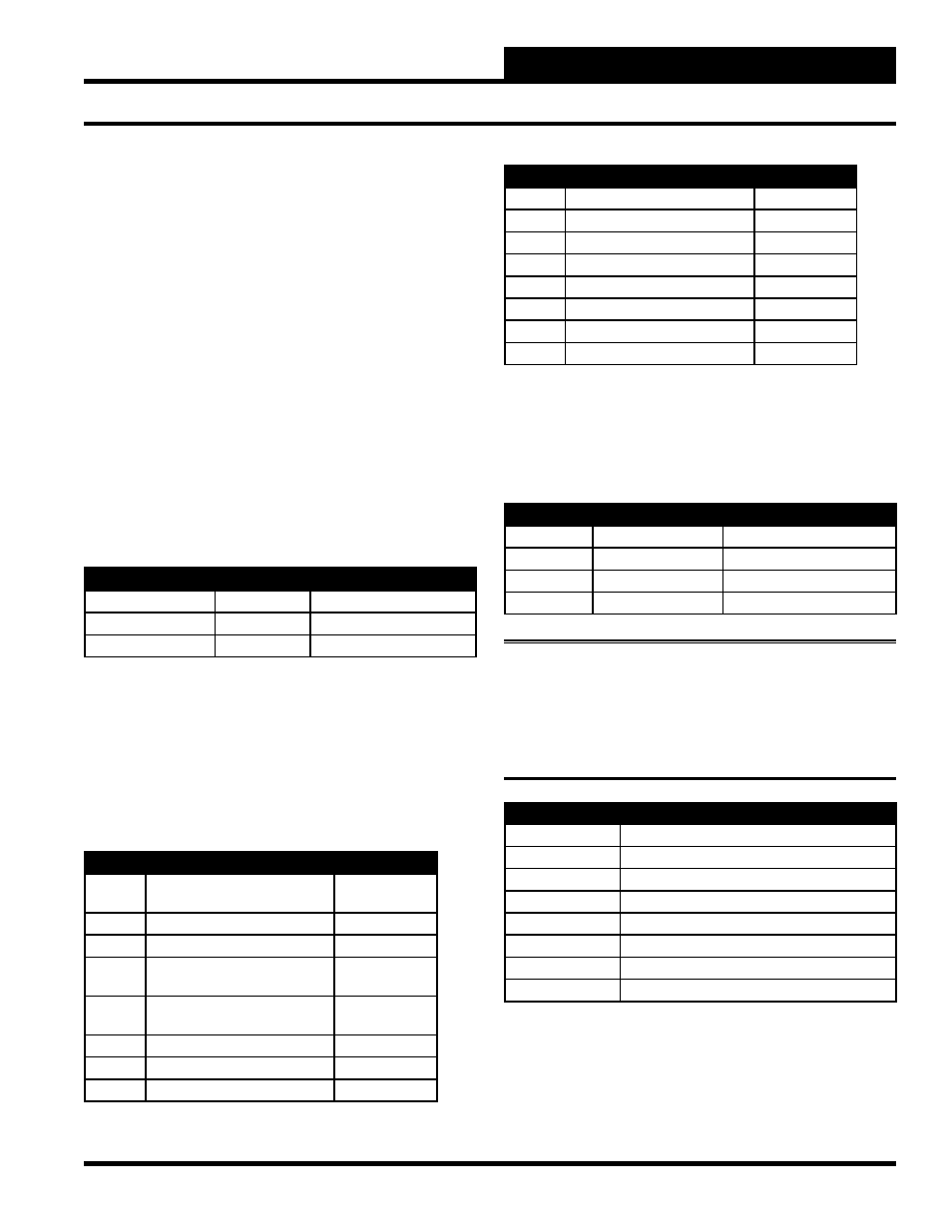
For example, assume that you have three different areas in a
building that have different schedules as shown in the following
table.
Area
Occupied Time
Week Schedule #1
1st Floor West
8:00 am - 5:00 pm, M-F
Week Schedule #2
1st Floor East
7:00 am - 7:00 pm, M-F
Week Schedule #3
2nd Floor
9:00 am - 4:00 pm, M-Th
Week Schedule #1 is named W1, and the value of W1 will be On
between 8:00 am and 5:00 pm, Monday through Friday, etc.
The Name column in the table that follows is the name that you
should use when specifying a point address to the system. The “n”
is where a “point number” for the point address is to be entered.
Table of Point Addresses
Name
Description
Value
Cn
Comparator (See analog input
screen binary setpoint)
On/Off
An
Analog Inputs
Analog
Pn
Analog Inputs
Analog
KnH
Control Outputs
(H Contacts)
On/Off
KnC
Control Outputs
(C Contacts)
On/Off
RnA
Data Registers (a)
Analog
RnB
Data Registers (b)
Analog
TnR
Trend Logging Run Time
Analog
Name
Description
Value
TnC
Trend Logging Change of State
None
TnA
Trend Logging Analog Trend
None
TnP
Trend Logging Analog Peak
None
Ln
Logical Input
On/Off
Wn
Week Schedules
On/Off
Sn
Optimal Starts
On/Off
GBn
Binary Globals
On/Off
GAn
Analog Globals
Analog
Constant Point Addresses
The following list shows several point addresses within the
system that are always available for use on many of the data input
screens.
Name
Description
Associated Data Type
0
Logical Zero
Always Off
1
Logical One
Always On
////
Logical Null
Ignored
. . . .
Logical Off
Always Off/Not Used
Note:
When a point option is not required, replace the default
value (/ / / /) with either a zero (0) or dot (. . . .) to force the
system to realize that the option is always OFF. If the slashes
are not replaced, the system will ignore that input and the
system can, in rare cases, see the slashes as being ON.
Name
Description
Analog 0
Initiates a 0 (zero) value
TIME
Current Time (in HH:MM format)
TIMEB
Current Time (in minutes-since-midnight format)
NEWSEC
New Second
NEWMIN
New Minute
NEWHR
New Hour
NEWDAY
New Day
NEWMON
New Month