Measurement Computing DBK Part 2 User Manual
Page 92
DBK48, pg. 12
967792
8B Isolated Signal Conditioning Module
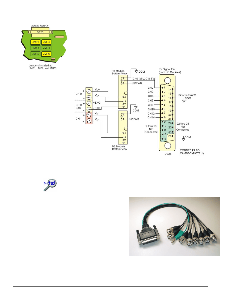
Bringing Eight 8B Module Outputs to the DB25 Signal Output Connector
With 3 jumper networks installed [one per socket] in JMP1, JMP2, and JMP6 the
signal output connector is pinned out as shown in the following figure. This only
brings the outputs of eight of the 8B modules, i.e., Ch 0, 2, 4, 6, 8, 10, 12, and 14.
When the Signal Output connector is pinned-out in this manner it can be used with a
CA-208-3 cable to bring the 8 channels out to the cable’s BNC connectors for easy
connection to other measuring equipment.
DB25 SIGNAL OUTPUT Pinout with JMP1, JMP2, JMP6 Installed
This configuration brings channel 0, 2, 4, 6, 8, 10, 12 and 14 outputs to the DB25
Signal Output Connector.
If the DBK48 is not connected to a Daq device via the P1 connector, then remove the Rnets
from S01 and S02. These resistor networks connect each 8B module’s output to the
multiplexer for P1.
Use the CA-208-3 cable as follows:
1. Connect the DB25-end of the CA-208-3 cable
directly to DBK48’s 25-pin Signal Output
connector.
2. Connect the CA-208-3 analog common banana
plug to the local ground of the measuring
equipment.
3. Connect the CA-208-3 BNC connectors (for
channels 1 through 8) to the measuring
equipment.
Note 1: CA-208-3 connects directly to the signal output connector. However, another cable, which looks virtually the
same, is the CA-208 (with no”-3” extension). If you are using a CA-208 you must first connect a CA-35-18
cable to the DB25 connector on the DBK48; then connect the CA-208 to the CA-35-18 cable. For CA-208
users, a wiring diagram is provided immediately following the DBK48 specifications section.