Configuring the dbk65 address – Measurement Computing DBK Part 2 User Manual
Page 135
Configuring the DBK65 Address
You can connect 1 or 2 DBK65 modules to a single main channel on the primary data acquisition device.
Thus, a 16-channel Daq device can support up to 32 DBK65 modules. Since each module has 8 input
channels, a fully populated system can use 256 input sensors (32 modules x 8 channels per module).
To keep the large number of inputs organized, each DBK65 module is given a unique address via its DIP
switch, S1 [located on the rear panel].
CAUTION
Each DBK65 must be configured before connecting the module to inputs and outputs.
In addition, adjustment of the channel address must only be performed when the
system’s power is OFF. Failure to do so may result in equipment damage.
S1’s four leftmost micro-switches are used to set the module’s channel address in binary. Set the micro-
switches to the desired address only after ensuring that the system power is OFF. Several example address
settings are provided below. Other settings can be easily derived.
Each DBK65 module in the system must have a unique channel address for the primary
data acquisition device. Valid addresses are 0 to 15. Note that two modules can have a
setting for the same primary channel, for example, two modules could be set to channel
0; as long as one module is set to “L” to indicate the lower sub-channels 0-7 and the
other is set to “U” to indicate the upper sub-channels of 8-15. Examples of various
settings follow.
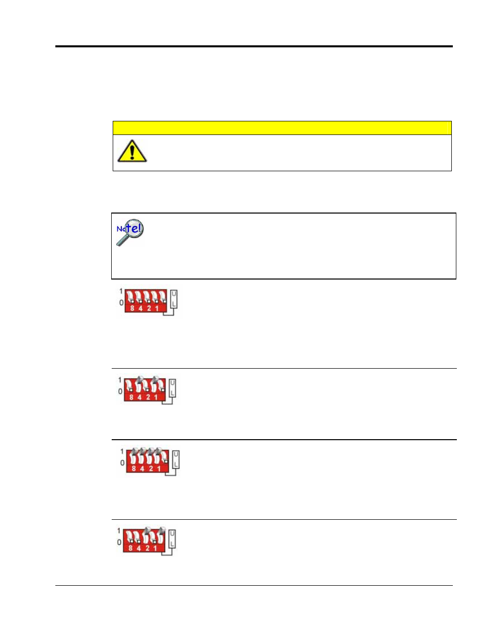
Channel 0 / Lower
Primary Acquisition Device Channel 0
DBK65 Lower Sub-Channels 0-7
The four leftmost micro-switches are set to “0” (Open). This sets the unit to
primary acquisition device Channel 0. The rightmost switch is at “L,”
setting the module to the “lower” DBK65 sub-channels (0 through 7).
Note: If connecting a second module to primary device Channel 0, the U/L
switch for that module would be set to “U” for sub-channels 8 thru 15.
Channel 5 / Lower
Primary Acquisition Device Channel 5
DBK65 Lower Sub-Channels 0-7
The micro-switches for binary 4 and binary 1 are closed. This sets the unit to
primary acquisition device Channel 5. The rightmost switch is at “L,”
setting the module to the “lower” DBK65 sub-channels (0 through 7).
Channel 15 / Lower
Primary Acquisition Device Channel 15
DBK65 Lower Sub-Channels 0-7
The micro-switches for binary 8, 4, 2, and 1 are closed, thus setting the
channel to “15” (8 + 4 + 2 + 1) for the primary acquisition device. The
rightmost switch is at “L,” setting the module to the “lower” DBK65 sub-
channels
(0 through 7).
Channel 2 / Upper
Primary Acquisition Device Channel 2
DBK65 Upper Sub-Channels 8-15
The micro-switch for binary 2 is closed, thus setting the channel to “2” for the
primary acquisition device. The rightmost switch is at “U,” setting the module
to the “upper” DBK65 sub-channels (8 through 15).
DBK Option Cards and Modules
988793
DBK65 pg. 7