Connecting dbk90 modules to other devices – Measurement Computing DBK Part 2 User Manual
Page 179
DBK Option Cards and Module
907492
DBK90 pg. 5
Connecting DBK90 Modules to other Devices
Mounting DBK90 Modules to Each Other –
Using Kit # 1109-0800
Each 1109-0800 mounting kit includes two splice bars and eight screws. The kit is only intended for
mounting one DBK90 module to another. However, other kits are available for mounting DBK90s to
primary acquisition devices, for example, to a DaqBook/2000 Series device. Those kits are discussed
shortly.
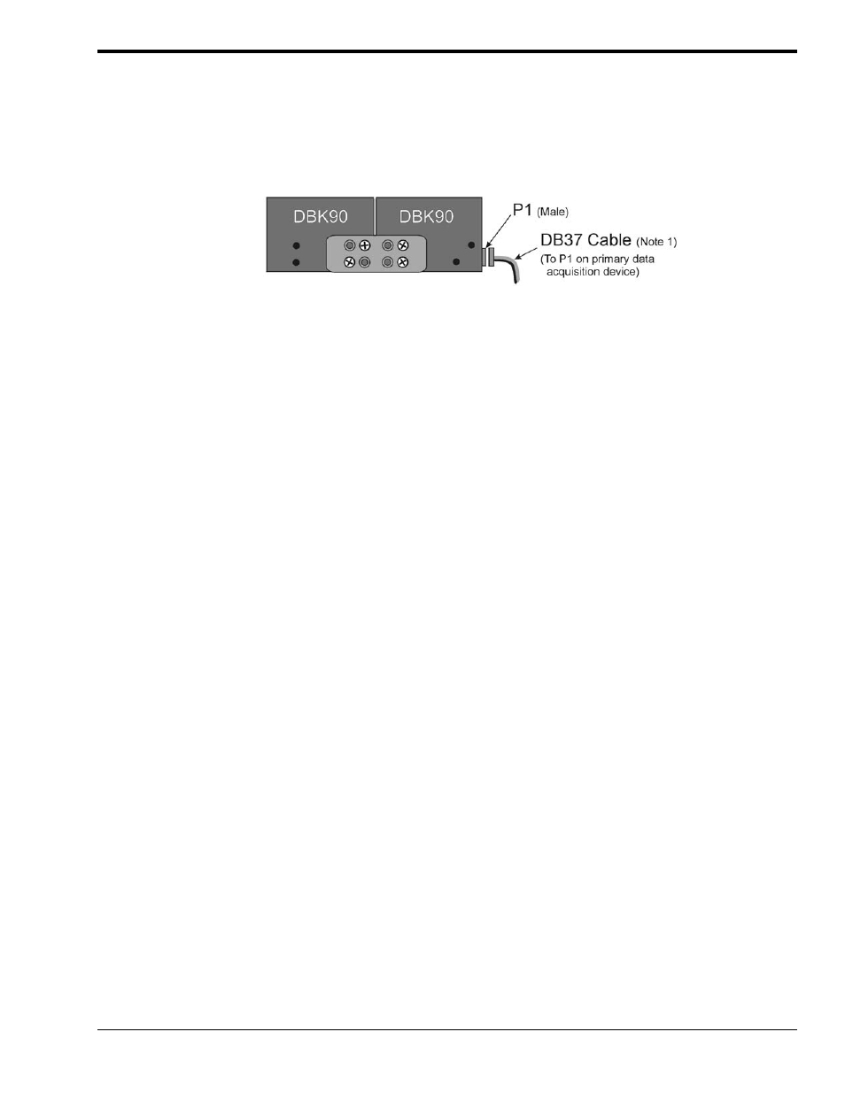
Two DBK90 Modules, Combined via Kit # 1109-0800
Follow these steps if you desire to mount DBK90 modules to each other using 8-hole splice bars.
1. Push the two DBK90 modules together such that their P1 connectors properly mate. Note that
each DBK90 has a female P1 DB37 connector on one side and a male P1 DB37 connector on
the other.
2. Align four holes of an 8-hole splice bar as indicated in the preceding figure. Note that the two
holes for one DBK90 will be vertical, while the two holes for the other DBK90 will be
diagonal (see figure).
3. Secure the splice bar to the DBK90 modules using the provided screws.
The screws are 8-32 x 1/4 Phillips Pan Head Screws.
4. Use the second splice bar and set of 4 screws, to secure the other side of the assembly.
Note: Additional splice bar kits can be used to add more DBK90 modules to the assembly.
5. Connect one end of a DB37 cable to the DBK90 male P1 connector (see figure).
6. Connect the other end of the DB-37 cable to the male P1 connector located on the primary data
acquisition device.
This completes the procedure.
Note 1: A female-to-female 37 pin connector can be used to connect a DBK90 to the host data
acquisition device. The use of a CA-143-x shielded cable is recommended for scenarios in
which signal noise is a problem. Page 14 of this section includes a list of cables compatible
with DBK90 use.