Measurement Computing DBK Part 2 User Manual
Page 48
DBK43A & DBK43B, pg. 28
899892
DBK Option Cards and Modules
For all of the strain gage channels that are to be adjusted, set their ranges to +5V.
Click the DBK Parameters tab to expose the strain gage signal conditioning programmable settings.
Click the Attach button to substantiate a connection between the PC and the LogBook.
Adjust the Excitation - DBK16
For DBK16, set the excitation voltage for the transducer by adjusting the trimpot labeled EXC and
measuring the voltage with a voltmeter across the +EXC and -EXC on the bridge or at the terminals of the
signal conditioning module.
Adjust the Excitation - DBK43A - DBK43B
DBK43A and DBK43B are equipped with a switch that allows the excitation voltage to be read by the
LogBook and displayed in LogView. For a DBK43A orDBK43B to be adjusted, you must:
1. DBK43A users: Reposition the DBK43A’s “physical” calibration switch to the CAL position.
DBK43B users: Position DBK43B’s CAL1 and CAL2 to the calibration position.
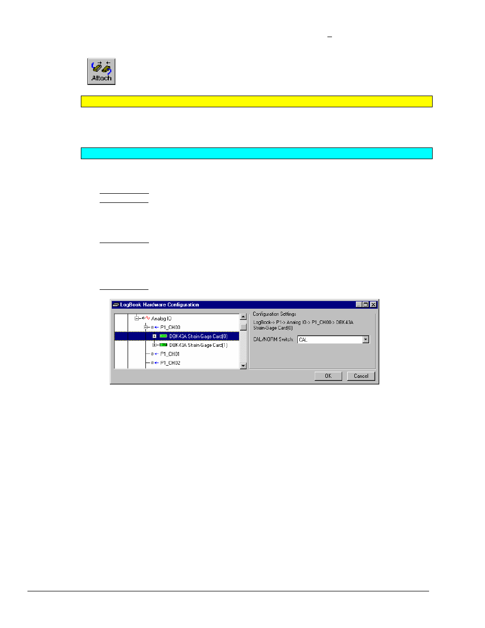
2. Select CAL in LogView. Open the LogBook Hardware Configuration window and select the
appropriate DBK43A (see following figure).
DBK43A users: In the Configurations settings box, set the CAL/NORM Switch to CAL. If the
DBK43A is not displayed click the + to the left of the base channel (to which it is attached), this action
expands the hardware tree in the LogBook Hardware Configuration window. Repeat this process for
all DBK43A units that are to be adjusted. Click OK to lock in the changes.
DBK43B users: In the Configurations settings box set the software switch parameter to
1’CAL+2’CAL.
Setting a DBK43A Cal/Norm Switch to “CAL”
3. In the Param1 column (see next figure for location), select all of the DBK43 channels that are to be
adjusted.
4. Set Mode equal to Excitation from the drop down list (located above the DBK Parameters tab).
5. Turn off all the channels in the system except for those DBK43A channels that are to be adjusted.