Using the p3 header, Caution – Measurement Computing DBK Part 2 User Manual
Page 217
Using the P3 Header
CAUTION
Disconnect the DBK202, DBK203, DBK203A, DBK204, or DBK204c from power and
from signal sources prior to connecting the CA-60 cable to the 40-pin header.
Take ESD precautions (packaging, proper handling, grounded wrist strap, etc.)
Use care to avoid touching board surfaces and onboard components. Only handle
boards by their edges (or ORBs, if applicable). Ensure boards do not come into
contact with foreign elements such as oils, water, and industrial particulate.
Do not confuse connectors. Ensure that you only connect P1 I/Os to P1, P2 I/Os to P2,
and P3 I/Os to P3. Improper connection may result in equipment damage.
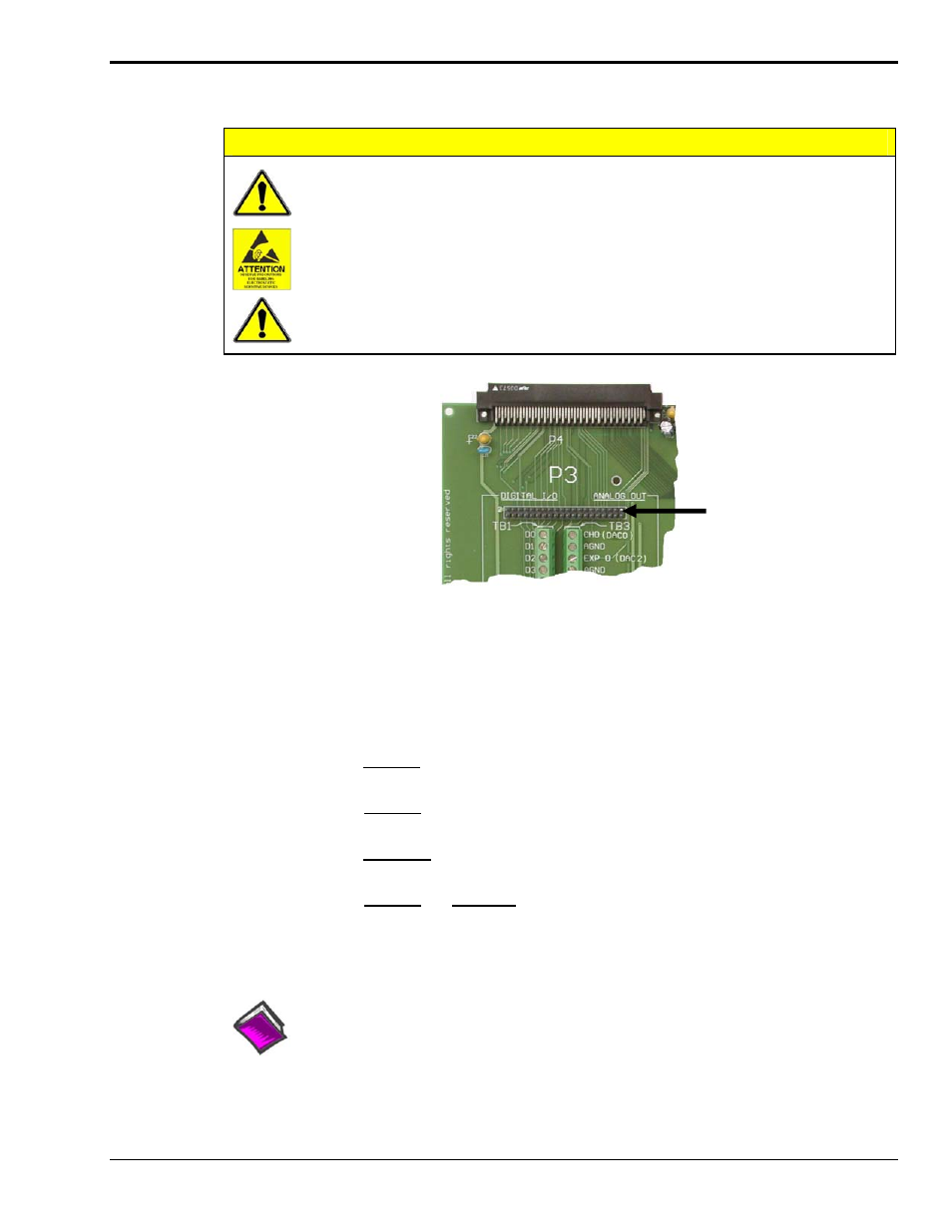
P3 40-Pin Header
If you need a DB37 connector
for P3, connect a CA-60 cable
to this 40-pin header.
The P3 Corner Section of a DBK202
The P3 40-pin header can be used to obtain a DB37 type connector via a CA-60 cable.
To make a DB37 connector available for P3:
1.
Follow the preceding CAUTIONS and ensure power is removed from the system devices.
2.
Access the terminal blocks:
a) DBK202 – access of the board is direct, or as determined by your own custom
enclosure.
b) DBK203 – Loosen the two thumbscrews on the front panel and slide the card
drawer free of the unit.
c) DBK203A – Remove the upper inside screw from each of the four corner brackets
(see figure, page 2) and lift the cover plate from the unit.
d) DBK204 and DBK204c – Follow step 2b or 2c as applicable to your unit.
3.
Connect the CA-60 cable to the 40-pin header.
4.
Return the system to normal operation.
Reference Note:
There is no direct pin-to-pin correlation between the pins on the header and those on the
DB37 connector. For P3 pinout information refer to chapter 2, System Connections and
Pinouts.
DBK Option Cards and Modules
938994
DBK202, DBK203, and DBK204 Series, pg. 11