Measurement Computing DBK Part 2 User Manual
Page 51
DBK Option Cards and Module
899892
DBK43A & DBK43B, pg. 31
V
LC
= (10 * 2.05×10
-3
) = 20.5 mV
If 1000 pounds were applied, we would see 6.833 mV. This is arrived at as follows:
(1000/3000) * 10 * 2.05×10
-3
= 6.833 mV
Using the Calculated Maximum Voltage to Determine the Necessary Gain
To maximize the resolution and dynamic performance of the system, the sensor’s output should be
amplified to correspond to the data acquisition system’s input range.
Using the LogBook’s +5V input range, the required gain is calculated by dividing 5V by the maximum
output voltage of the sensor. Before performing the calculation, it is typically a good idea to pad the
maximum sensor voltage by about 5% so that, once amplified, it won’t bump into the limit of the 5V range.
G = V
LB
/ (V
GO
+ V
GO
* 5%)
Where:
G
= Gain
V
LB
= LogBook input range
V
GO
= Maximum gage output
For the strain gage in the previous example with a maximum output of 10.5mV, the required gain is:
G = 5.0V / (0.0105V + 0.0105V * 0.05) = 453.5
For the above load cell with a maximum output of 20.5mV, the required gain is:
G = 5.0V / (0.0205V + 0.0205V * 0.05) = 232.3
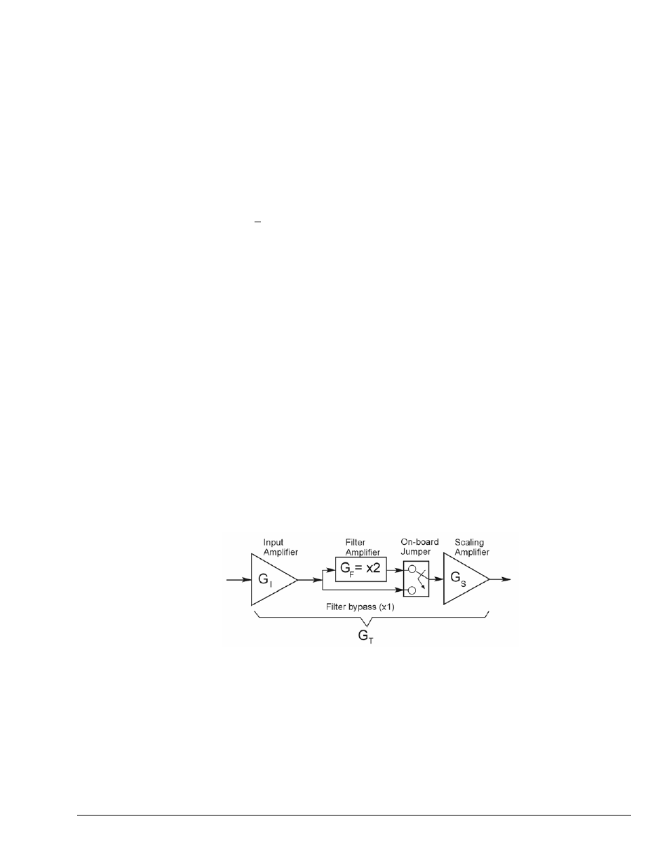
Determining the Gain of Each Amplification Stage
The system’s total gain is:
G
T
= G
I
* G
F
* G
S
Where:
G
T
= Total gain
G
I
= Input amplifier gain
G
F
= Filter gain
G
S
= Scaling amplifier gain