Measurement Computing DBK Part 2 User Manual
Page 74
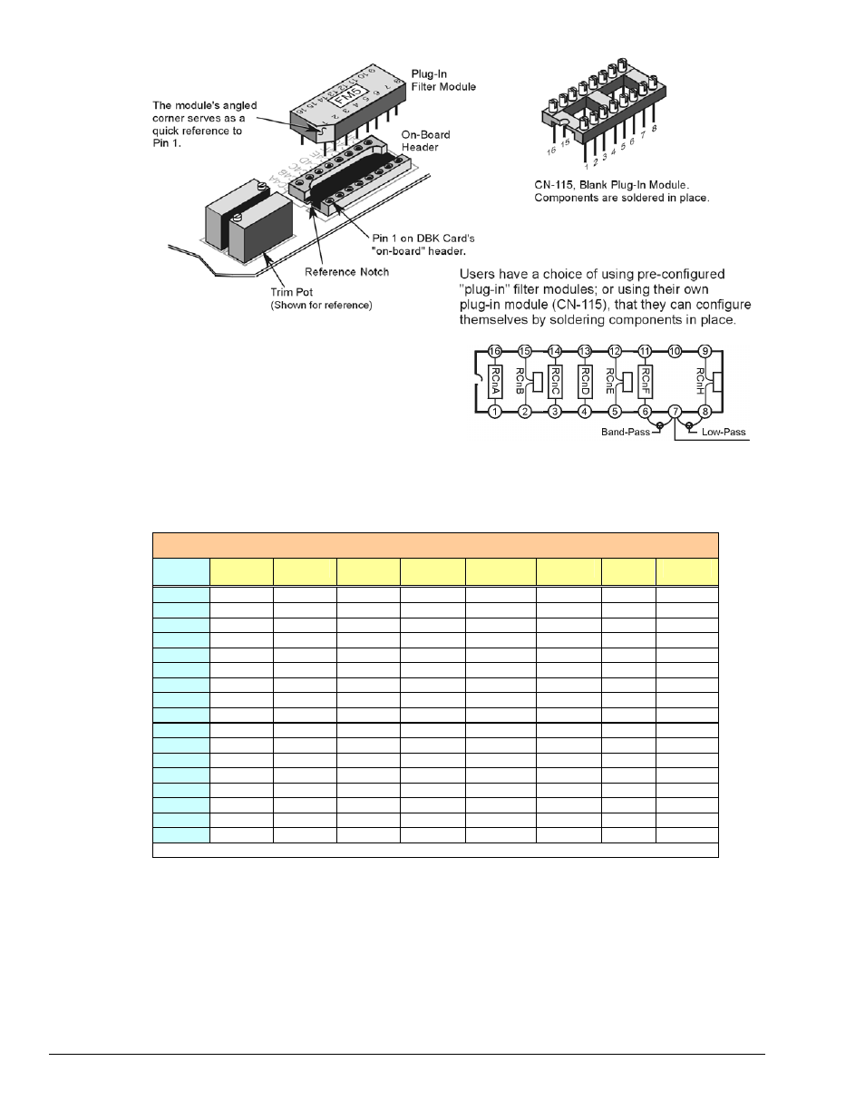
The right-hand figure shows the DIP-16
component pattern typical of the 4 filter sections.
Note: “n” corresponds to “channel number.”
Pin 7 of the DIP-16 socket:
•
connects to pin 8 for low-pass filtering
•
connects to pin 6 for band-pass filtering
DIP-16 Component Pattern
The following table lists values of components for common corner frequencies in Butterworth filters. If
designing your own filter, software from Burr-Brown provides the component values to create the desired
filter. Note that the design math is beyond the scope of this manual.
3-Pole Butterworth Filter Components
3dB
(Hz)
RCnA
RCnB
RCnC
RCnD
RcnE
RCnF
RCnG
RCnH
0.05
3.16 MΩ
1 µF
none
3.16 MΩ
1 µF
3.16 MΩ
none 1
µF
0.10
1.58 MΩ
1 µF
none
1.58 MΩ
1 µF
1.58 MΩ
none 1
µF
0.20
787 kΩ
1 µF
none
787 kΩ
1 µF
787 kΩ
none 1
µF
0.50
3.16 MΩ
0.1 µF
none
3.16 MΩ
0.1 µF
3.16 MΩ
none 0.1
µF
1
1.58 MΩ
0.1 µF
none
1.58 MΩ
0.1 µF
1.58 MΩ
none 0.1
µF
2
787 kΩ
0.1 µF
none
787 kΩ
0.1 µF
787 kΩ
none 0.1
µF
5*
3.16 MΩ
0.01 µF
none
3.16 MΩ
0.01 µF
3.16 MΩ
none 0.01
µF
10*
1.58 MΩ
0.01 µF
none
1.58 MΩ
0.01 µF
1.58 MΩ
none 0.01
µF
20
787 kΩ
0.01 µF
none
787 kΩ
0.01 µF
787 kΩ
none 0.01
µF
50
3.16 MΩ
0.001 µF
none
3.16 MΩ
none
3.16 MΩ
none none
100*
1.58 MΩ
0.001 µF
none
1.58 MΩ
none
1.58 MΩ
none none
200
787 kΩ
0.001 µF
none
787 kΩ
none
787 kΩ
none none
500*
316 kΩ
0.001 µF
none
316 kΩ
none
316 kΩ
none none
1000*
158 kΩ
0.001 µF
none
158 kΩ
none
158 kΩ
none none
2000
78.7 kΩ
0.001 µF
none
78.7 kΩ
none
78.7 kΩ
none none
5000
31.6 kΩ
0.001 µF
none
31.6 kΩ
none
31.6 kΩ
none none
10000
15.8 kΩ
0.001 µF
none
15.8 kΩ
none
15.8 kΩ
none none
*These pre-configured Butterworth frequency modules are available from the manufacturer.
You have the option to configure the filter sections as band-pass filters rather than low-pass filters. The
component selection program provides band-pass component values. The program also computes and
displays phase and gain characteristics of the filter sections as a function of frequency.
DBK45, pg. 4
987696
DBK Option Cards and Modules