Bridge applications – Measurement Computing DBK Part 2 User Manual
Page 26
DBK43A & DBK43B, pg. 6
899892
DBK Option Cards and Modules
Bridge Applications
There are several ways to hook-up strain gages—all are configured into a 4-element bridge (the 4 legs in a
bridge circuit). The quarter-, half- or full- designation for a strain gage refers to how many elements in the
bridge are strain-variable.
quarter bridges - have 1 strain-variable element
half bridges - have 2 strain-variable elements
full bridges - have 4 strain-variable elements
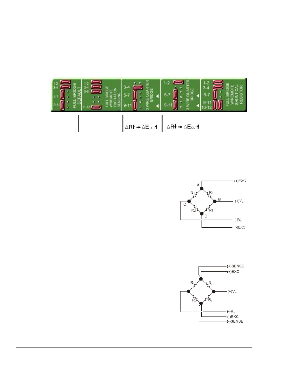
DBK43A and DBK43B boards include a silkscreen pictorial aid, as indicated in the following figure. On
the boards, the image appears between the channel inputs and Headers H100 through H400.
FULL BRIDGE
DEFAULT
FULL BRIDGE
WITH REMOTE
EXCITATION SENSING
3 WIRE QUARTER
BRIDGE
3 WIRE QUARTER
BRIDGE
FULL BRIDGE
WITH REMOTE
SHUNT CAL RESISTOR
On-Board Silkscreen Aid for Configuring Jumper Headers H100 through H800.
Each channel of the strain gage module has locations for bridge-completion resistors when using quarter-
and half-bridge strain gages. These resistors are fixed values necessary to fill out the 4-element bridge
configuration.
The following is a standard symbol for a 4-element bridge type strain gage. The figure makes use of
bridge-completion resistor designations for a module’s channel.
Any or all of the 4 resistive elements may be strain-
variable. Where an element is a fixed resistor, the
fixed resistor may be installed in the internal location
provided. Note that n is the channel number +1.
For an internal resistor on channel 7, the location is
R800E.
If R1-R4 is a fixed resistor it may be placed internally in the Rn
locations on the resistor plug. “n” is the channel number + 1.
R1 = Rn00F; R2 = Rn00C; R3 = Rn00E; R4 = Rn00B.
Example: R3 in channel 7 = R800E location.
Bridge Completion Resistors
Connections are provided for Kelvin-type excitation.
The excitation regulators stabilize the voltage at the
points connected to the on-board sampling dividers.
Unless you run separate sense leads to the excitation
terminals of the strain gage, the voltage regulation is
most accurate at the terminal blocks on the DBK43A
or DBK43B. In a Kelvin-type connection, six wires
run to a 4-element strain gage, and the excitation
regulation is optimized at the strain gage rather than at
the terminal blocks. This connection works with as
little as 10 feet of 22 gauge lead wire if accuracy is
critical. (See Full-Bridge with Remote Excitation
Sensing Configuration in full-page figure.)
Kelvin-type Excitation Leads