Dbk65 power requirements, Power available for transducers, Dbk65 voltage regulation – Measurement Computing DBK Part 2 User Manual
Page 130
Each of the 8 channels can be set for a different excitation voltage. 5, 10, 15, and 24 VDC are provided
internally from the DBK65 and are selected via placement of a jumper. In addition, a fifth jumper position
can be used to select a custom voltage between 5 and 20 VDC. The user must install a resistor if this
option is desired. The following section, Customizing a Voltage, contains additional information.
Each channel includes 2 screw terminals that allow for a relay closure. Designated as CAL+ and
CAL-, the terminals can be used to switch in a calibration resistor for 6-wire transducers. Note that the
DBK65’s rear panel CAL switch will open or close the internal calibration switches for all 8 channels
simultaneously.
DBK65 Power Requirements
The amount of DC power required, which is supplied to the DBK65 through its Power-In DIN5 connector,
is 15 V @ 833 mA, 20 V @ 625 mA, assuming max load. In addition, the amount of power drawn from
the P1-based host acquisition device, such as a Daq device or a LogBook is 25 mA from ±15 V, 750 mW
total. For purpose of our discussion here, a P1-based device is one which is connecting to the DBK65 via
the DB37 (P1) connector.
Power Available for Transducers
At the excitation voltages available from the DBK65 (5 to 24 V) a single transducer will typically draw
from 10 to 100mA. This fact and the per-channel and per-module current limits must be taken into account
to avoid overloading the system.
•
Total current available, for all 8 channels: 240mA.
•
Current available for a single channel: 100mA.
•
Transducer, typical current draw: 10 to 100mA
DBK65 Voltage Regulation
Better voltage regulation results in a lower variance of the source output voltage [excitation voltage], as
load is applied. Graphs depicting DBK65 voltage regulation for excitation set at 5, 10, 15, and 24 V are
included with the product’s specifications.
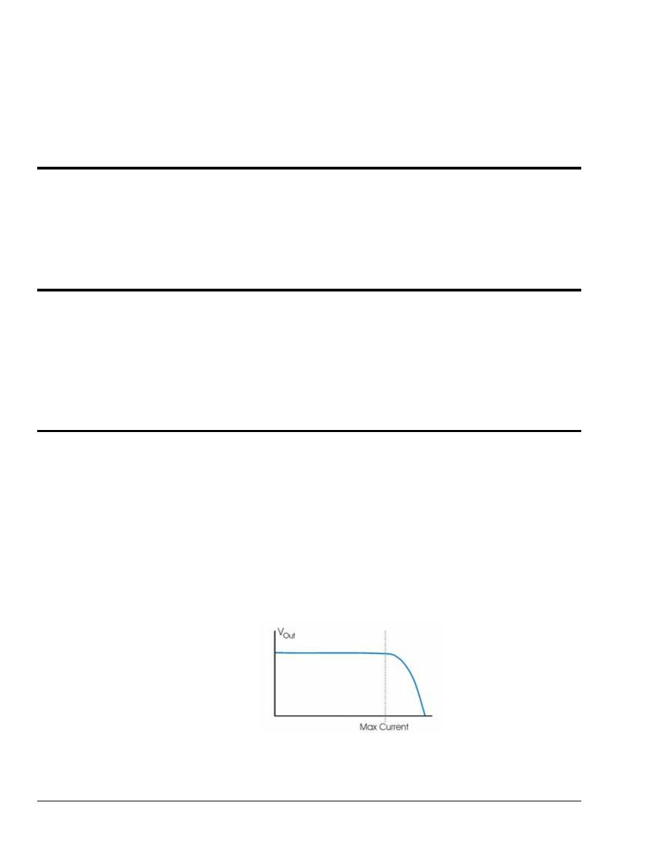
The following graph is intended to provide a better understanding of voltage regulation. In the graph, the
output voltage (V
Out
) exhibits less than ±5% variance from nominal voltage, i.e., 5, 10, 15, or 24 VDC.
This also applies to the user settable 5 to 20 VDC.
The ±5% variance factor holds true up to the limiting current (Max Current). Refer to the graphs at the end
of Specifications for typical voltage and current values.
Typical Current Limiting Voltage Curve
DBK65 pg. 2
988793
DBK Option Cards and Modules